THE NORTON COMMANDO DIAPHRAGM SPRING CLUTCH.
1. Index.
2. Introduction.
3. The Commando diaphragm spring.
Description of its parts.
4. The gearbox mounted motor cycle
Qualities they should possess.
A small survey friction clutch.of the
qualities they do posses.
5. Clutches torque and oil
6. Basic differences between DRY and
between wet and dry clutches.
7. The Norton primary oil bath chain case
History and ‘development’ of.
Which clutch Norton put within it...
8. The DRY Norton Commando diaphragm
Required clutch torque calculations for the
spring clutch.original 750 clutch and, in theory,
clutch torque capacity.
Ramifications had the clutch been correctly
designed as a wet clutch.
9. The stop gap Atlas Mk3 or Commando
A bit of history.
as it was later named.
10. How the Commando clutch actually works.
Easy to understand.
11. The clutch lift mechanism.
Test results comparing Dommy and
Commando.
12. A development Atlas Mk3 clutch.
What we could have ended up with….
.
13. Setting up the Commando diaphragm spring Why it is set at this deflection point.in a new
fully engaged clutch
14. A LITTLE warning.
Ramifications of altering deflection point of
spring to obtain lighter clutch lever action.
15. Different Commando diaphragm spring Facts.
comparison chart .
16. The vastly overweight bronze plated Reasons for use of bronze plates?
Clutch gearbox breaking/flywheel/ clutch
torque calculations. Tales heard.
fitted to later Commando models.
17. Physical differences in the diaphragm Some data from the Laycock Eng.
Drawing. springs employed un Commandos
clutches


1


18. A couple of points.
19. Waffle.
20. Some really ‘clever’ ideas for Commando May the gods protect us!!
clutches.
21. Haussermann. An apology. A statement.
THE END OF THE CLUTCH EPISTLE


2
The Atlas Mk3 / Commando frame problems / fiasco.
Clutch basket / centre / plate spline wear. A possible reason.
One reason for Dommy and Commando cranks becoming 4 part. Quality
Control??
The missing Dominator cam shaft oil bath. One reason why cams fail
prematurely?
And yes I did try to get the crankshaft stress raiser removed and the camshaft oil
bath replaced.
Stainless steel wheel spindles. Some personal thoughts ONLY and NOT advice.
Cork clutch friction material. Why Triumph employed it? Ramifications of using it….
Our transmission shock absorbers. (or increasers?).
Our primary chain efficiency. 98%? Pure fiction?
The Commando gearbox. Reliability. Have failures caused serious injury or
death?
Rotating rocker shafts. A reason for the problem.
The Commando disc front brake. Original design criteria as I understood it.
Some possible reasons for it not working as well as expected which some may not have
considered..
‘Super blend’ main bearings. Waffle .
Barrels.
Speeding up oil pumps.
Exhaust systems. Another, eventual, quick learning curve.
Petrol taps causing carburetion problems.
THE BELTS WE USE FOR PRIMARY DRIVES….
INTRODUCTION.
A FACT.
A QUICK(?) HISTORY OF THE BELTS WE EMPLOY FOR PRIMARY DRIVE.
UNIROYAL / GATES. MEANING OF ‘STOCK’ BELTS.
BELTS AND OIL
BELT AND BELT DRIVE MISINFORMATION.
A FEW EXAMPLES OF BELT AND BELT DRIVE MISINFORMATION.
COMPARING VARIOUS BELT MANUFACTURERSPOWER TABLES.
OUR/MY BELT DRIVE PROBLEMS.
MOTOR CYCLE PRIMARY BELT TENSION. A REAL BIGGY.


3
NORTON ODDS AND SODS
2. INTRODUCTION.
Since the Atlas Mk3 or Commando as it was later named was introduced probably more fiction than fact has appeared in magazines and on the web regarding its diaphragm
spring clutch.
This is being written to give anyone interested FACTS about the clutch such as how it
‘works’. Why Norton employed several different diaphragm springs in the clutch while
Commandos were in production; with each new spring ‘stronger’ than the previous one
which resulted in not only increasing the amount of torque the clutch would transmit before
slip occurred but also in clutch lever action increasing from the ‘light’ easy two finger
operation of the original 750 clutch to ridiculously heavy on the later 750 and 820 models.
How altering the overall height of the clutch plates to give lighter OR heavier clutch lever
action also results in decreasing OR increasing the torque the fully engaged clutch will
carry before slip occurs, along with the causes of the slip and drag problems the clutch is
‘prone’ to suffering from.
Unlike at least one other web page on this subject this one will have been checked and
corrected if required before being placed on the web to try to ensure it is at least clutch-
wise technically correct.
The Gentleman very kindly doing the clutch checking for me is the retired Engineering
Director and Chief Clutch Designer of Laycock Engineering of Sheffield. Laycock
Engineering being a company who at one time designed and manufactured diaphragm
spring clutches and overdrive units for much of the British, European and USA automobile
industry. The ‘Gentleman’ / Laycock Engineering also designed probably the World’s first
motor cycle diaphragm spring clutches (single and twin friction plate) in the early 60s for
the Villiers Starmaker unit construction engines. Laycock manufactured the diaphragm
springs for them and later, the various slightly different diaphragm springs used for
production Commando and rotary Norton clutches.
Unfortunately, to fully understand how the Commando diaphragm spring clutch works and
why it can and often does give clutch slip and drag problems a small knowledge of very
simple clutch ‘basics’ is required and I propose to cover these first for those not fully aware
of them. I then propose to deal with the type of clutch Norton decided to employ within
their new primary oil bath chain case (OBCC from here on) when designing developing
and introducing it around 1932/4 and then, using the original 750 Commando clutch for the
example, to demonstrate with a few very simple clutch calculations why Norton continued
to employ a clutch designed to be run DRY which they placed within their new OBCC.
I will then show some of the ramifications had they of employed a ‘WET’ clutch that would
work CORRECTLY with oil mist or oil on the clutch friction interfaces within their new
OBCC.
The Villiers Starmaker, Commando and rotary clutches were all based on a
‘Haussermann’ clutch design.
fiction than fact has appeared in magazines and on the web regarding its diaphragm
spring clutch.
This is being written to give anyone interested FACTS about the clutch such as how it
‘works’. Why Norton employed several different diaphragm springs in the clutch while
Commandos were in production; with each new spring ‘stronger’ than the previous one
which resulted in not only increasing the amount of torque the clutch would transmit before
slip occurred but also in clutch lever action increasing from the ‘light’ easy two finger
operation of the original 750 clutch to ridiculously heavy on the later 750 and 820 models.
How altering the overall height of the clutch plates to give lighter OR heavier clutch lever
action also results in decreasing OR increasing the torque the fully engaged clutch will
carry before slip occurs, along with the causes of the slip and drag problems the clutch is
‘prone’ to suffering from.
Unlike at least one other web page on this subject this one will have been checked and
corrected if required before being placed on the web to try to ensure it is at least clutch-
wise technically correct.
The Gentleman very kindly doing the clutch checking for me is the retired Engineering
Director and Chief Clutch Designer of Laycock Engineering of Sheffield. Laycock
Engineering being a company who at one time designed and manufactured diaphragm
spring clutches and overdrive units for much of the British, European and USA automobile
industry. The ‘Gentleman’ / Laycock Engineering also designed probably the World’s first
motor cycle diaphragm spring clutches (single and twin friction plate) in the early 60s for
the Villiers Starmaker unit construction engines. Laycock manufactured the diaphragm
springs for them and later, the various slightly different diaphragm springs used for
production Commando and rotary Norton clutches.
Unfortunately, to fully understand how the Commando diaphragm spring clutch works and
why it can and often does give clutch slip and drag problems a small knowledge of very
simple clutch ‘basics’ is required and I propose to cover these first for those not fully aware
of them. I then propose to deal with the type of clutch Norton decided to employ within
their new primary oil bath chain case (OBCC from here on) when designing developing
and introducing it around 1932/4 and then, using the original 750 Commando clutch for the
example, to demonstrate with a few very simple clutch calculations why Norton continued
to employ a clutch designed to be run DRY which they placed within their new OBCC.
I will then show some of the ramifications had they of employed a ‘WET’ clutch that would
work CORRECTLY with oil mist or oil on the clutch friction interfaces within their new
OBCC.
The Villiers Starmaker, Commando and rotary clutches were all based on a
‘Haussermann’ clutch design.
4
3. THE COMMANDO CLUTCH DIAPHRAGM SPRING.
This comprises of three parts …
1. The spring. This is the outer approximately 22 mm wide ring known as a
BELLEVILLE SPRING. A French Gentleman named Julian Belleville originally
developed this type of spring in the 19th century.
2. The steel ‘lump’ in the middle is known as the RELEASE RING.
3. The 18 RELEASE EARS or RELEASE FINGERS. These extend from the release ring
to the inner edge of the Belleville spring.
The only function of the release ears in a normal Haussermann diaphragm spring clutch
is to transfer deflection applied at the release ring to the Belleville spring to deflect it so
as to engage and disengage the clutch.
An explanation of ‘normal’ as used in 3 above. The last plate we place into the clutch
is the cast iron plate known as the PRESSURE PLATE and on it is a raised lip known
as the PRESSURE LINE which is the contact point with the diaphragm spring through
which the Belleville spring applies the load to clamp the clutch plates together. In a
‘normal’ Haussermann diaphragm spring clutch the pressure line makes contact with
the Belleville spring portion of the diaphragm spring at a point just outside the inner
edge of the Belleville spring and NOT on the release ears as on the Commando ‘clutch’.
This contact point is often referred to as the inner fulcrum, the outer fulcrum being just
inside the outer edge of the Belleville spring where it is located in place by a circlip /
retaining ring. The early 1960s Villiers Starmaker single and twin friction plate
diaphragm spring clutches had the pressure line in this ‘normal’ ‘correct’ ‘standard’
‘usual’ position as can be seen on the drawing of the two friction plate version shown
on page 54 of the book ‘British 250 Racers’ or in the original ‘Motor Cycle’ 21-Feb-63
report. Personally I refer to the Commando clutch pressure line position on the release
ears / fingers as a bodge but the clutch designers in both the UK and USA I have talked
with about it whilst picking their brains on other clutch subjects (such as the use of
‘carbon’ etc friction materials) are far more polite than I am and have used words such
as ‘unusual’ ‘interesting’ and ‘unique’ to describe it. I will later offer an explanation as to
why the pressure line position was moved on to the release ears for the Commando
clutch. I would add that in my opinion the Commando clutch was the best DESIGN of
multi plate friction clutch fitted to any British twin cylinder motor cycle of that era, in spite
of the bodge
5
4. THE GEARBOX MOUNTED MOTORCYCLE MULTI PLATE-FRICTION CLUTCH.
Our gearbox mounted multi plate friction clutches are SUPPOSED to possess a few
basic qualities according to, for example, Mr Philip Irving in his book ‘Restoring and
Tuning Classic Motor Cycles’, the Staff of The Motor Cycle in their book ‘Speed and
How to Obtain It’ and Mr Victor W. Page in his 1916 American motor cycle bible ‘Early
Motor Cycles Construction - Operation - Service’.
These qualities may also be given in other books on my shelves such as Mr Nicholson’s
‘Modern Motorcycle Mechanics’, books in my local library and possibly papers
presented by motorcycle designers a century plus ago to The Institute of Mechanical
Engineers (I.M.E.) or The Society of Automobile Engineers (S.A.E.). Papers that would
now be held in their libraries and in the books regularly published by each Society and
now sitting on people’s book shelves probably gathering dust. An example on my shelf
is the I.M.E. General Discussion on Lubrication, 1937 with Vol. 2 containing a paper
‘The Lubrication of Chains with Particular Reference to Transmission Chains of the
Roller Type’ by Mr R. Coulson of the Renold and Coventry Chain Co. Ltd. of which there
will be more, later…
SOME of the qualities our multiplate friction clutches are SUPPOSED to possess are
that they will…..
1. NOT slip when fully engaged, even when hot.
2. Free off INSTANTLY and without drag whenever required, even when hot.
3. Be EASILY operated by the user at all times.
4. Possess the LIGHTEST rotating weight reasonably possible.
Several decades ago I began to take an interest in dry primary belt drives and
diaphragm spring clutches as a means of improving British bike performance for both
race and road use thanks to somewhat higher primary drive efficiency (mainly in the mid
and higher rpm range) and as a means of simply and easily without any major costly
redesign obtaining a clutch that possessed all the above qualities. One thing I decided I
should do before writing this would be to confirm, yet again, just to be on the safe side,
that owners still suffered the same clutch problems as I and my friends had in the 60s
and 70s when our BSA Norton Triumph AMC Enfield etc motorcycles were our main
form of transport and sometimes even enjoyment…
6
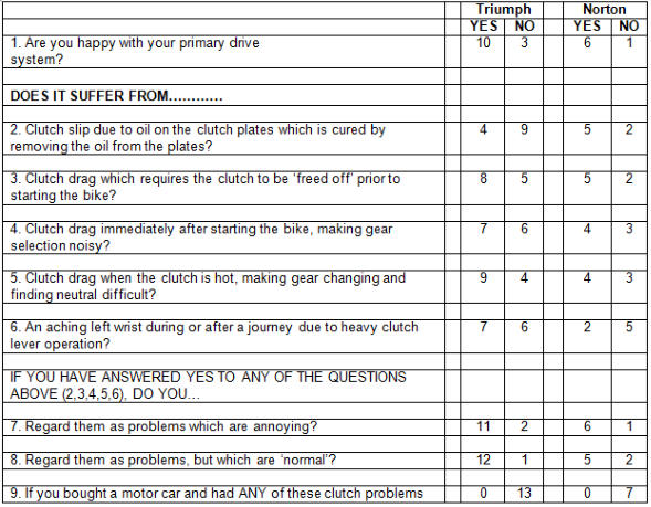
Thus, one Saturday afternoon many years ago in a friends London British bike spares
emporium I conducted a little survey among the visiting customers asking each one if
they would kindly fill in the clutch questionnaire I handed out. Many kindly did so and
the results yet again confirmed that my clutch experiences whilst riding British motor
cycles produced in the 50s, 60s and 70s were perfectly ‘normal’.
The following motorcycles were represented that afternoon:
Triumph: 5 x T140; 1 x TR7; 2 x 6T; 1 x T120; 2 x T100; 2 x T90.
Norton: 2 x 820 Commando; 2 x 750 Commando; 1 x 650SS; 2 x 99.
BSA owners were very few and far between so I have not bothered to include them.
7

5. DRY AND WET CLUTCHES, TORQUE AND OIL.
Dry clutches are designed to work correctly with dry friction interfaces and wet clutches
are designed to work correctly with oil mist or oil on the friction interfaces and both types
will, if CORRECTLY designed, manufactured, maintained AND used for the application
for which they were designed, possess ALL the basic qualities given earlier.
However, if you place a designed to be run dry clutch within an OBCC (remember, it’s
an Oil Bath Chain Case!) and the oil required to lubricate the great many plain bearings
within the chain to try to keep chain efficiency above say 90% at the high primary linear
chain speeds we often use then works its way into the clutch and onto the dry friction
interfaces one should NOT be surprised when clutch slip and drag due to oil become a
problem, especially if the OBCC is over filled to start with (and I wonder how many
Commando owners reading this, those still using a primary chain that is, fill their OBCC
as per section K8 in the 750-850 Commando Workshop Manual rather than filling to the
level plug? I wonder how many even use the correct type and grade of oil?).
Clutch slip can also occur if a manufacturer employs a clutch that is sub-minimal in
torque capacity such as those fitted to Triumph T140s which were, so Triumph claimed
in their Workshop Manuals, ‘designed to run in oil’.
The torque capacity of a clutch (the amount of torque it will in theory carry before slip
occurs) is calculated by multiplying 4 factors together and using the old Imperial unit for
torque of Foot Pounds (Ft Lb.) they are:
1. The number of friction interfaces. (Early Commando with 4 friction plates
giving 8 friction interfaces. A later version with 5 sintered bronze friction plates
giving 10 friction interfaces).
2, The effective radius in feet (ft.) of the friction interfaces. (Clutches with 4 solid
fibre DON International asbestos containing 06.1339 friction plates or today’s
equivalent asbestos free Surflex friction plates approximately 0.205 ft. and later
sintered bronze friction plate clutches approximately 0.21 ft.)
3. The clamp load in Pounds force (Lbf.) being applied to the friction interfaces
by the diaphragm spring.
4. The Coefficient of Friction (C of F from here on) acting between the friction
plates and steel inter plates.
REGARDING the effect of oil or oil mist on the C of F values of clutch (and brake)
friction materials.
A rule of thumb for ANY clutch / brake friction material is that the DRY C of F value is
THREE to FOUR times GREATER than the WET C of F value and an example is the
material employed for the original Commando friction plates. The Norton factory
drawing show they had postage stamp sized ‘lumps’ of Ferodo MS6 material bonded to
the steel core (till they fell off resulting in drag problems as is documented in the N.O.C.
Commando Service Notes) and the Ferodo MS6 data sheet lists the C of F values to be
used for design purposes as Dry 0.34. Oil mist 0.1 – 0.12. Immersed in oil 0.09. For
sintered bronze rule of thumb values are Dry 0.3 and Wet 0.06-0.08. Example: Ferodo
SM3 ‘suitable for dry use’ 0.26 and Ferodo SM6 ‘intended for wet use’ 0.07.
The Laycock Eng. Gentleman employed 0.06 for all his wet / in oil sintered bronze
friction material clutch designs referring to the use of 0.08 as “being a bit optimistic’.
8
Certainly there are friction materials giving higher wet and dry C of F values for design
purposes than these just given but the rule of thumb still applies. However many
materials are only suitable for dry OR wet use and one example of a DRY use only
material was Ferodo MZ41 as used in for example Gold Star clutches (1954-56 on the
friction plates and on the chain wheel to the end of Gold Star production) for which the
Ferodo data sheet states and I quote ‘it is unsuitable for use with oil’ while giving
only a dry C of F value to be used for design purposes of 0.41. The data sheet for the
later Don International solid fibre asbestos containing Commando friction plates
(06.1339 - DON 112 material) gives only a dry C of F against temperature curve
showing it to be 0.35 at 100 - 200 C rising to 0.4 at 400 C.
9
6. THE BASIC DIFFERENCES BETWEEN DRY AND WET CLUTCHES
In view of the much lower C of F values due to oil / oil mist it must surely be obvious to
all that any clutch employing a friction material that can be employed both dry and wet
will (when fully engaged and before slip occurs) transmit, by rule of thumb, at least 3
times more torque when dry than it will when wet. It thus follows that for the wet clutch
to possess the same in theory torque capacity as the dry clutch the wet clutch requires
to employ at least 3 times more friction interfaces or a 3 times greater effective radius to
the friction interfaces or a 3 times greater load clamping the friction interfaces together
OR a smaller combination of 2 or all 3 of them simply to offset the much lower C of F
value due to oil.. All having ramifications that had to be considered by the motor cycle
manufacturers when introducing their primary OBCC designs, ramifications such as
wider clutches requiring a wider OBCC, greatly increased rotating weight / mass, new
lift mechanisms to give the extra lift required to free off the greater number of friction
interfaces and much heavier clutch lever action unless going for hydraulic operation
which would require a redesign and increased manufacturing costs.
It has been my experience that very few British motor cycle owners - along with some
supposed British motor cycle experts and belt drive system makers - are aware of even
the basic FACTS concerning the effects of oil on clutch design and performance.
The oil bath CHAIN case was designed by Englishman Harrison Carter in 1896
(according to Motor Cycle Sport April 76 Page 147 in an excellent article on chains)
although a photo of my late Father on his late 20s Norton shows an open (for the World
to gawp at in wonder) primary chain, possibly with a drip feed lubrication system with
extra lubrication being supplied by mud, water, stones or any animal / human flesh and
bones caught up in it which could explain the photo showing him to be wearing leather
despatch riders boots protecting his lower leg.
I believe that at the time Norton were getting around to developing their pressed steel
primary OBCC Sunbeam were busy removing their secondary OBCC, probably
because it did not give the ‘race bike look’ and was reducing sales? (I was told by a
cyclist friend that Sunbeam sensibly retained them on their push bikes!). I ‘hear’ from a
Gentleman servicing rotary Nortons that there are many with over 70,000 miles on their
clocks still using their original Renold G.P. rear chain and sprockets with lots of
adjustment still available. Another friend with an ex-police Interpol 2 purchased the bike
with the original rear chain in perfect condition with over 80,000 miles (further testament
to efficiency of the OBCC). Apparently one Gent who is using an ex-police rotary for
courier work has over 200,000 miles on the clock and is still on the original chain and
sprockets but of course the rear chain on these bikes is employed within a proper
OBCC, thus giving the chain the correct lubrication and such items do not give the race
bike look….do they? Of course the Gentleman did mention that the owner kept the
OBCC correctly filled with oil and replaced any failing oil seal when required both of
which I would guess helps chain life !!….’
10
7. THE NORTON PRIMARY OIL BATH CHAIN CASE AND CLUTCH. (And those of
other manufacturers)
Whilst it is most certainly NOT the description I personally EVER used as clutch slip
occurred and engine revs instantly rose to well beyond the 7000rpm I was usually
nearly at (or at) when it occurred (and which I considered the safe max for normal use
with my Dommy) in the book ‘Speed and How to Obtain It’ the staff of ‘The Motor Cycle’
most politely refer to the idea of enclosing a clutch within an OBCC as ‘frankly a
compromise’ and dare to suggest ‘a much better idea’ is to enclose the chain within the
OBCC along with lots of oil to lubricate, keep cool and more efficient the many plain
bearings within the chain whilst employing the clutch externally so it can be employed
dry BUT this ‘much better idea’ was of course more costly to produce so few British
manufacturers adopted it. Ariel did so and the front page of ‘Motor Cycle’ (29-01-53) for
example had a full page advert proclaiming ‘The ARIEL dry 3 plate clutch’ showing it
mounted externally to the OBCC beneath a simple cover held on with a couple of
screws…
Norton finally came around to the idea of employing a pressed steel primary OBCC
around 1932-34 when an economic recession was well under way resulting in low bike
sales - which was probably not helped in Norton’s case by having an old road model
range. Thus I very much doubt that they had anything like enough money or time
available to introduce the major redesigns that would have been required had they
introduced the new road model OBCC employing a correctly designed wet clutch within
it, one that would for example free off instantly without drag whenever required, or a dry
one running externally as Ariel did. Thus Norton adopted the ‘frankly a compromise’
idea but continued to employ a DRY clutch which they placed within the new OBCC and
for the 1930s with road bike power outputs and the situation at the time a reasonable
double compromise which gave and still did give in the 60s and even now on our old
Nortons reasonably good service IF maintained correctly.
To keep the oil required to (in theory) lubricate the many plain bearings within the chain
from entering the dry clutch Norton placed the oil level plug very low down so oil at the
correct level only just about touched the lower run of the chain creating an oil mist in
service, placed what is described in the parts books as an ‘oil excluding band’ around
the basket and employed a recently developed Ferodo friction material that was not
physically effected by a tad of oil contamination. (i.e.: it did not fall apart when oil
eventually made its way inside the clutch but the rule of thumb C of F reduction due to
oil mist / oil still applied). At the same time they removed the crankshaft mounted shock
absorber (or increaser) and probably copying one that had been in use decades
previously (as Triumph I understand did after WW2 when introducing one into their
clutch) placed a shock absorber (or increaser) within the new clutch. For those thinking
“but it is called a shock absorber so it must be one”, a quote from one of Mr J Williams
design / development note books, this one from the early 50s for the AJS 7R and E95
models ‘Cush drive on slower running sprocket while desirable has insufficient play’.
There will be some waffle on the subject later.
11
Owners were also told to use a smear of grease on the rollers supporting the basket
when assembling a clutch.
Yes I know one British belt system maker who uses a belt he claims is oil proof or
resistant tells people that oil is required to lubricate the rollers but I can only
assume he has not read or understood for example the ‘Maintenance Manual and
Instruction Book’ for models 50, ES2, 88, 99, 650, 750 Atlas and 750 scrambler
(publication P106/P) which on page 36 states ‘apply a little medium or anti-
centrifuge grease’ (another Norton book states ‘a smear of grease’) to the rollers
and on page 87 states that one possible cause for clutch slip problems to be ‘OIL
ON PLATES (USUALLY CAUSED BY OVERFILLING).’
What a relief it is to know that owners are to blame and not Norton for shoving a
designed to be run dry clutch within the OBCC in the first place!
The remedy given in the manual to cure the slip problem due to oil being to
‘DISMANTLE CLUTCH AND WASH PLATES IN PETROL’ which was a ritual we would
often perform in our brain dead death defying (and failing in some cases) full-throttle-
just-about-everywhere-possible days of youth (and I suspect in most cases mechanical
ineptitude when it came to maintaining our bikes correctly). (Kent County Council or
someone did NOT name and sign part of the A20 towards London from Brands Hatch
and Johnson’s cafe ‘Death Hill’ all those years ago just for something to do! I noticed
the other day as I drove past in my warm dry reliable no fun boring box that it has been
renamed ‘Gorse Hill’ with ‘Formerly Death Hill’ written beneath).
This ritual of dunking clutch plates in petrol was probably practised by generations of
British bike owners all round the World many possibly having overfilled their OBCCs
assuming, incorrectly in most cases, that as the clutch was within it then the clutch must
be designed to work correctly with oil in it so some extra oil to allow for leaks would not
matter and it might have helped if the manufacturers had placed the oil level plug
correctly to lessen the chance oil had of working into the dry clutches. It was only
decades after having owned a Plumstead Plonker (AMC Matchless or AJS motorcycle
produced at Plumstead) and suffering from my fair share of slip and drag problems and
practising the clutch plate dunking ritual that I noticed my AMC books state ‘The
presence of oil in the front chain case does not affect clutch efficiency providing the oil
level does not exceed 1/8inch from the bottom of the filler orifice’. Personally I had
regarded the chain inspection cover as the filler orifice and the low down plug as the oil
level hole and I bet I was not alone in doing so!
I also note that that on page 23 of the book ‘AJS’ Mr Neill states ‘ Do not put oil into the
clutch as it was designed to be run dry’. I understand (from an ex NVT friend) that it was
the late John Nelson (at Norton and investigating the Commando clutch slip problem)
who cut up a Commando chain case and inserting some Perspex into it to see exactly
what was occurring within it that resulted in the later 750 / 850 Commando Workshop
Manual stating ‘Under no circumstances allow more than 7 fl oz (200cc) of oil in primary
case’. (Section K8 in the manual). Naturally section K9 tells owners to fill to the oil level
plug! I wonder who the ‘brain’ responsible for that was?
I talked a friend with a large collection of Commandos into draining down his only
remaining chain primary drive one (which had oil in it to the level plug) and it contained
290cc of oil. One Gentleman who knows just a ‘bit’ about Norton twins, especially
Commandos having won championships racing them in his younger days, told me he
fills his customers Commando chain cases with the bike on the side stand and lets the
oil dribble out of the level plug till it stops doing so and my money would be on this
giving something more like 200ccs worth of oil BUT only for those still using a primary
chain as he, unlike ‘some’ people, is fully aware that the Commando clutch and the
belts we use, even the Synchroflex AT10 belt, were designed to be run dry.
12
Many years ago I phoned Mr Hopwood and asked him for his views as a Motorcycle
Designer on the idea of employing a wet clutch within a motorcycle primary OBCC as
Triumph had done.
For those who are unaware… Mr Hopwood was responsible for the design of the
original Norton Dominator engine. In 1961 he resigned from being Managing Director at
Norton and moved to Triumph as a Director and General Manager, in 1964 became
Engineering Director and Deputy Managing Director and in 1971 was appointed to the
BSA Board with responsibility for motorcycle design engineering. In 1973 he resigned
and retired, later writing his book ‘Whatever Happened to the British Motorcycle
Industry’ in which he gives his reasons for resigning along with many examples of
British motorcycle industry mismanagement and incompetence and if - as a late British
motorcycle owner - you have not read the book why not? A good second hand copy is
cheap enough via ABE BOOKS on the web or use your local library and borrow a
copy.
For SOME later Norton examples of Engineering and management incompetence,
find a copy of ‘Motor Cycle Sport’ (January 77) and on pages 27 and 28 read the
facts about the Commando main bearing fiasco and its many causes and
solutions. After 30 odd years of sending copies to Norton owning friends (especially
Commando ones!!) I noticed the other day that someone has managed to put a copy on
the web.
After a bit of a silence as he composed his thoughts Mr Hopwood replied and I quote “In
my opinion it is a perfectly acceptable idea for smaller capacity lower powered motor
cycles but, had I had my way, all the larger capacity higher powered motor cycles for
which I was personally responsible would have had dry clutches”. (Mr Hopwood gave
me permission to quote his reply if I ever wanted to do so - and gave his reply slowly so
I could jot it down).
Mr Hopwood’s Norton and BSA twin designs both employed dry clutches but for the
BSA they fully enclosed the dry clutch that was employed within the OBCC as I believe
Rudge had done previously. The later BSA / Triumph 3s also employed a dry clutch
although the person responsible for the clutch design kept one friend busy and probably
fully funded his racing over the years as he reduced their considerable static and
rotating weight for his customers. I suspect the designer of the BSA/Triumph 3 clutches
thought they were for a car attached to the crankshaft flywheel so their excess weight
would not matter and the engine manufacturer could reduce their flywheel weight to
compensate if required as I believe Ford once did many decades ago for a Laycock
Eng. clutch which came in a tad overweight.
Mr Nicholson in his ‘bible’ Modern Motor Cycle Mechanics states of Mr Hopwood’s dry
BSA twin clutch that most problems with it are due to oil working in as the clutch was
intended to be run dry. I bet 95%+ of problems with the clutch were / are owner related.
Decades ago, whilst visiting Mr Phil Heath at his home to drop off some new olde
Norton single valves I mentioned my Dommy clutch slip problem. (Some of Mr Heaths’
motorcycle racing history can be found on the web). Mr Heath told me that he had been
involved at Norton with the Norton OBCC development and that I should fill my OBCC
as he did on his Norton’s by doing the following:
13
Strip clutch and wash everything in petrol to remove all traces of oil. Remove any glaze
from the friction material. Reassemble the clutch correctly using a SMEAR of grease on
the rollers. Adjust both chains CORRECTLY. (I.E. the primary first with your or
someone’s foot resting on the secondary chain ‘loading’ the primary as you do so).
Replace the OBCC outer leaving the oil level plug in place but remove the inspection
cover. Remove spark plug/s. Find someone and with that someone turning the motor
over on the kick starter SLOWLY fill the OBCC through the inspection hole with straight
SAE10 or 20 engine oil whilst watching the chain and as soon as I noticed oil was
JUST TOUCHING the chain STOP FILLING.
He made the comment that it would stop the problems of slip and drag due to oil
entering the clutch for many thousands of miles use but that it did very little for chain
life…. which amused me. Ever seen the published Renold (Industrial) chain spec and
noted the power levels, chain speeds and lubrication systems recommended? They are
nothing like how we employ our primary chains and as far as I am aware Renold never
published a motor cycle chain spec. (A waffle on chain and chain efficiency will appear
later).
HINT. If you cannot stop your Norton pressed steel primary OBCC from leaking try
buying and fitting a new seal BEFORE pretending you are a totally unskilled metal
basher and fully ruining the chain case outer. - It’s amazing how much the seals can
reduce in size over the years. A look at the patent drawings for the Norton OBCC shows
exactly how the seal was designed to seal. I must have spent a fortune on tubes of
gasket ‘gunge’ trying to seal mine over the years till I finally bought a new seal and
instantly solved my leak problem!
Of course a dry running belt requires no oil…not even the designed to be run dry
Synchroflex AT10 belt in which case the seal is only required to keep crap out…
Incidentally, whilst Norton to my knowledge never actually stated publicly that their
clutches were designed to be run dry BSA did. If for example you look in ‘The Gold Star
Book’ on page 130 you will see reproduced the BSA 1949 B32 Gold Star publicity sheet
which states the clutch is ‘BSA multi dry plate with oil resisting fabric inserts’. (My first
car clutch dry friction material was ‘oil resisting’ which did not fall apart from oil
contamination when a seal leaked but the clutch suffered from slip problems due to the
oil when torque was applied to it going uphill etc..). I note BSA conveniently left ‘DRY’
out of their clutch description in later publicity sheets. I wonder why when in the 50s
they were employing dry use only Ferodo MZ41 friction material? Did some owners
write in asking them to explain why anyone would put a dry clutch in an OIL BATH
CHAIN CASE (let us NOT forget!!) and was it the cause of their slip and drag problems?
The OBCC filling instruction given in ‘The Gold Star Book’ being to fill till oil can be
seen, via the inspection cover hole, to be just touching the lower run of the chain. If you
look further in the book, the parts drawings show the basket formed an oil excluding
band around the clutch. Nor were Norton and BSA the only British motorcycle
manufacturers to not only adopt the ‘FRANKLY A COMPROMISE’ OBCC idea but to
also employ a designed to be run dry clutch within it not that some belt system
makers are aware of this fact…..
14
The oil excluding band was certainly fitted to Norton ‘Burman’ clutches as shown in my
1956 edition of ‘Norton. All models from 1932’ by Mr E. M. Franks but were not fitted to
my AMC/Norton clutches when I started playing with them and learning the ancient
ritual of ‘dunking’ clutch plates in petrol. Had AMC/Norton realised by then that many
owners were overfilling their OBCC and the band was merely retaining more oil within it
than it was supposed to be excluding so did not fit them?
Were they removed when loss making AMC mismanagement told profit making Norton
in Birmingham that they had to reduce the cost of the clutches they were producing for
the whole AMC group and as they were already being produced at a loss by Norton
(‘Whatever Happened to the British Motor Cycle Industry’ page 150) was the oil
excluding band removed to save money? Or were they never fitted to AMC Norton
clutches? Who now would know or even care?
As a dry belt convert for several decades I most certainly do not care. My Dommy was
straight off the track with no lights or kick-start, Manx clutch and as a joke to make it
street legal… a bulb horn!
15
8. THE DRY NORTON COMMANDO DIAPHRAGM SPRING CLUTCH.
In his book ‘A Racing Legend - Norton’ Mr Jim Renolds correctly describes Dominator
and Commando clutches as being DRY clutches within OBCCs. Mind you, American
Cycle World road tests for the Atlas shown in the book ‘Norton Dominator Performance
Portfolio 1949 – 1970’ describe the clutch as being DRY PLATE twice, IN OIL MIST
once and WET PLATE twice thus covering all options…! But, that’s motor cycle experts
or ex-spurts for you of whom there have always been a LOT more of the latter than the
former where British bikes are concerned, especially these days on the web, on web
forum sites and in club and other magazines etc. Many British road test writers,
probably totally confused, ‘played it safe’ only stating that the chain ran within the OBCC
and / or along with giving the chain size.
A gentleman calling himself ‘Dyno Dave’ (a British bike expert?) appears to believe that
Norton would not place a designed to be employed DRY clutch within their OBCCs and
tells the World exactly that in his Commando clutch web page so to demonstrate the
facts, whilst proving Mr Renolds correct and ‘Dyno Dave’ incorrect; what now follows
are a few simple very basic clutch calculations for the original 750 Commando.
These are then followed by some wet clutch calculations to demonstrate the
ramifications had it been correctly designed as a wet oil mist clutch - similar
ramifications that would also have applied when Norton had to decide which sort of
clutch to employ inside their new-fangled primary OBCC in the mid-1930s.
When designing such lumps one designs for the worst case - i.e. max torque which is
what I in my younger days tried to use much of the time! The books give a max crank
torque output of 48 ft lb. With std. 26 –57 tooth sprockets and assuming (incorrectly) no
power loss in the primary chain then max torque at the clutch = 48 x 57/26 = 105 ft. lb.
(Torque in ft lbs. = H.P. x 5252 divided by RPM. Thus, retaining the same H.P. if you
reduce the revs as you do at the slower rotating clutch you increase the torque). To this
torque value a designer now applies a service or safety factor to allow for the impulsive
nature of the motors power output, the vibration caused by the chain, shock loads from
the rear wheel etc.. And a rule of thumb service / safety factor given for clutches in one
ref. book in my local library is x 2. (Recommended Safety/Service factors for ‘industrial’
use can be found in belt and chain design manuals). The Laycock Engineering
Gentleman told me that he had used, depending upon the number of cylinders etc..,
around x 1.6 for multi cylinder engine car clutches and x 2.4 for say: a tractor, lorry,
bulldozer or earth mover / scraper clutch.
(Personally I use and suspect a factor of x 2 is not far out for our single and twin
cylinder motorcycle clutches and if my use of it is a tad high, it is erring on the side of
safety and, as the dry belt drive diaphragm spring clutches I sometimes cobble together
for friends road, scrambles, trials and race Norton, BSA and Triumph etc.. motorcycles
are easily operated with two fingers, weigh around 6 1/2lb or less with an aluminium
alloy centre for racing (splined shaft only) and do not suffer from slip (or drag) problems
so what if their clutches do carry a tad of spare torque capacity).
Thus using the rule of thumb x 2 safety / service factor the required clutch torque
capacity is 105 ft lb x 2 = 210 ft lb.
16
17
The clutch employed 4 friction plates giving 8 friction interfaces for which I am going to
assume an effective radius of 0.21 ft for the original friction plates. The original friction
plates (06-0749) were steel with, according to the Norton drawing, lumps of Ferodo
MS6 friction material bonded to them and the Ferodo data sheet for MS6 lists the C of
Fs to be used for design purposes as: Dry 0.34. Oil mist 0.1 – 0.12. Immersed in oil
0.09. With the ORIGINAL version of the diaphragm spring employed set up at the
‘correct’ / ‘normal’ / ‘usual’ / ‘standard’ deflection point at which the clutch was designed
to set it at; with new plates fitted and the clutch fully engaged, Norton’s own original test
results show it applied a clamp load of approximately 380 lbf. to the friction interfaces. A
Gentleman very kindly spent a lot of time looking for, eventually found and sent me a
copy of Norton’s original test results which were later confirmed as correct by having 2
original early Commando springs tested by the Mech. Eng. Dept. of a certain UK
Engineering University. I am NOT naming the University because they very kindly do
the odd bit of free mechanical testing for me and naturally as a poor old retired person I
want it to stay that way. Thus the in theory torque capacity of the clutch is….
DRY. 8 x 0.21 x 0.34 x 380 = 217 ft lb.
OIL MIST. 8 x 0.21 x 0.12 x 380 = 77 ft lb.
OIL IMMERSED. 8 x 0.21 x 0.09 x 380 = 57 ft lb.
As the required clutch torque capacity is 210 ft lb I would ‘suggest’ that, torque capacity
wise, it was a correctly designed DRY clutch and that Mr Reynolds is correct in stating
in his book that they are DRY clutches employed with an OBCC with Dyno Dave being
totally wrong in stating that Norton would not put a designed to be run dry clutch within
an OBCC.
As a clutch fitted to a 175 Bantam and swimming in oil it would probably be a well-
designed wet clutch (torque capacity wise ONLY that is)!
To demonstrate why the Commando employed a DRY clutch within the OBCC let us
play at designing the original 750 Commando clutch as a correctly designed (torque
capacity wise) oil mist WET clutch which would not, in theory, suffer from slip when fully
engaged when using the greater 0.12 C of F oil mist value given for design purposes for
Ferodo MS6.
It will show some of the effects of:
A. Increasing the number of friction plates,
B. Increasing the effective radius and
C. Increasing the clamp load.
Similar ramifications would have applied in 1932-34 as Norton were deciding what sort
of clutch to employ within the new OBCC. PLUS, if a wet clutch were employed there
would be a requirement for some form of mechanism to ensure the clutch freed off
instantly without drag whenever required - not that Triumph included such a device as it
was much easier AND cheaper to advise owners in the manuals to free off their clutch
before starting the motor - (1945-55 Workshop Instruction Manual No.11 page 22 for
example) - even if it did mean in ‘some’ cases stripping out the clutch to free it off… as I
remember occurring a few times. (And not just with Triumph clutches).
The last clutch I stripped out to free it off was a Norton one and, yes, we had first tried
the “dropping the fired up bike in gear off of the centre stand and into a brick wall
method” of freeing off clutches and failed, not that it does the transmission or forks
much good - but it might have worked - saving us time which was in serious short
supply.
(I will leave others to amuse themselves doing the following calculations using the lower
C of F of 0.1 given for Ferodo MS6 for oil mist application.)
I will leave others to amuse themselves doing the following calculations using the lower
C of F of 0.1 given for Ferodo MS6 for oil mist application.
A. INCREASING THE NUMBER OF FRICTION PLATES.
210 ft lb = X interfaces x 0.21 ft x 0.12 x 380 lbf..
X interfaces = 22.0 = 11 friction plates.
Ramifications of this are: More friction and inter plates and a heavier, wider clutch
basket and centre would be required; resulting in a serious increase in clutch static (and
more importantly) rotating weight. An increase in clutch width, requiring a wider OBCC
with its own consequences - foot pedal positioning for example. The major redesign and
expense in both money and time required to increase the lift given by the lift mechanism
to free off the clutch with its much greater number of friction interfaces whilst employing
a std. sized clutch lever that could be easily operated by the rider without going for
hydraulics which would have resulted in a major time consuming redesign and
increased costs. I suspect hydraulics would be required. We will not even think about
the effects of the even greater rotating (unbalanced?) clutch weight on the reliability of
the ancient gearbox. Remember, this was a gearbox which had originally been
designed for motor cycles putting a lot less ‘grunt’ through them than Commando
motors and with much lighter clutches on the end of the main shaft so far away from the
gearbox main bearing…
18
B. Increasing the effective radius.
210 ft. lb. = 8 x X ft. x 0.12 x 380 lbf.. X ft. = 0.575 ft.
Making the effective diameter of the friction interfaces 1.15 ft. or nearly 14 inches,
resulting in the outside diameter of the clutch becoming say 18+ inches!
Apart from the VAST increase in static (and more importantly rotating) weight, where
would you run the chain? If you ran it around this clutch with a larger engine sprocket to
give the same primary ratio then chain speed and thus chain mass would be so great
the chain would probably have escaped through your highly polished chain case -
possibly seriously damaging or amputating your leg in the process - before you reached
much above tick over rpm?
If you ran the chain on a much smaller sprocket behind it to reduce chain speed and
mass, you are shoving the vastly overweight lump / ‘clutch’ even further away from the
gearbox main bearing, a gearbox originally designed for use with clutches weighing
somewhat less than even a STD... early 750 Commando gearbox flywheel / ‘clutch’ with
once again the consequence of probable reduced gearbox reliability along with a much
bigger chain case being required with its own implications - especially that of ground
clearance when playing ‘boy racer’ cranking through left handers on your new sticky
tyres. Plus, could anyone really put up with all BSA and Triumph owners breaking into
song singing ‘three wheels on my wagon... just keep rolling along…’ as you arrived at
the pub for a Sunday lunch time pint or a club night meet / pint or two? I think not.
C. Increasing the clamp load……….
210 ft lb. = 8 x 0.21 ft. x 0.12 x X lbf.. X lbf. = 1042 lbf.
As I will try to explain why later, should you not already know, the load required for the
rider to apply to the release ring (for a std. Commando clutch) to start to free off the
clutch is approximately 55% of the clutch fully engaged clamp load value being applied
by the spring to the friction interfaces. Thus, with the original clutch and its’
approximately 380 lbf. clamp load then to start to free off the clutch the initial release
load required at the release ring was approximately 380 x 55% = 210 lbf.. - which as at
least one road test of the time reported gave nice very light clutch lever action - and
which gives a clutch lever that in my experience is EASILY pulled back to the bar and
held there with the clutch being drag free for as long as you want with a couple of
fingers, even when fitted to T140s and A65s etc..
Thus, with a clamp load of 1042 lbf. the initial release load would be 1042 x 55% = 573
lbf which is getting on for three times greater than the 210 lbf of the original Commando
clutch. 573lbf is also getting close to twice that of a late 750 / 820 Commando (circa 300
lbf initially) and well over twice as great as that required to start to free off that hand and
arm exercising often sworn about by owners who ride their bikes in London stop start
traffic T140 clutch lever action (249lbf initially according to Clymer) for which people
manufacture and people buy and fit hydraulic kits to make clutch lever action more
human friendly. Did not T140 adverts at one time suggest they were ‘a MANS bike’?
19
To increase clutch torque capacity for the 750 motor Triumph simply fitted 30% stronger
springs to the 650 ‘clutch’ even though the odd one or two earlier unit 650 British road
tests had actually DARED to mention their heavy clutch lever action. From memory, in
Motor Cycle Sport, one tester said of a unit 650 clutch something like… ‘It was as easy to
change gear without using the clutch as with - which was just as well as clutch lever
action was heavy’.
Perhaps Triumph had fitted 750 springs to it so it didn’t slip during the road test? It is
amazing how quickly 650 owners return to dealers moaning something awful if sold a set
of 750 clutch springs by mistake which they have then gone and fitted!
I wonder if Triumph referred to the use of stronger springs as clutch development?
Thus the complications of increasing the clamp load on a Commando would be the time
and expense required designing the hydraulic release system required, modifying the
existing set up to incorporate it along with the increased cost of a bike to the public and
all when trying and failing to compete for bike sales with motor cycles produced in
Japan…
There is always the option of increasing all three a bit but it still has the same results
even if on a smaller scale. As mentioned earlier there is yet another ramification which is
that a REAL wet clutch has mechanisms within it to ensure the plates, stuck together by
oil (stiction), free off instantly and without drag whenever required to do so.
I assume AMC / Norton did dimple the later coil spring clutch steel inter plates to try to
reduce stiction due to oil rather than simply because it looked pretty? One Motor Cycle
Sport late Triumph twin road test commented something like ‘As with the last Triumph
tested it was possible to start the engine with the clutch lever back to the bar’ and my
1950s Triumph factory manual recommends that owners free off their clutch BEFORE
starting their motors.
Of the Triumph stiction and drag due to oil problem when I once asked Mr Hele if he had
been aware of it while working at Triumph he replied either ‘It was a problem we never
did manage to cure’ OR ‘It was a problem we never did get round to curing’. (I did not
bother to note down his answer at the time as I was more interested in following Mr
Hopwood’s advice and ‘raiding’ Mr Heles’ memory banks regarding his experimental
experiences whilst at Norton of con rod length to stroke ratios).
Many testers probably wishing to protect their livelihood by not upsetting the motorcycle
manufacturers who paid to advertise in the magazines - and thus helped pay their wages
- merely mentioned in passing ‘early morning stiction’ or ‘a touch of early morning
stiction’ and NOT just for Triumph clutches either. I don’t suppose many, if any, reading
this ever read the tale told in American Road Racer magazine many years ago how the
Gent who started the magazine had previously lost his job after writing an HONEST road
test on a Japanese motorcycle for the magazine he was working for at the time - a bike
funnily enough made by a Japanese manufacturer with a very large U.S. advertising
budget!
20
A friend used to conduct and write the odd so called ‘classic’ race bike test and it was
amusing as to how many polite metaphors he could come up with to describe for
example ‘It handled like a poxy camel when ridden hard’ so the bike owner was not
upset and refused to make available other of their bikes for testing by the magazine.
NOT that the totally honest ‘It handled like a poxy camel when ridden hard’ would have
made it past the editor no matter how accurate the description!
A Triumph Manager told me that employees would park their Triumphs leaning against
walls with the clutch lever pressed back to the bar and, before walking in to work, give
the kick starter a jab or two to free off the plates to ensure the clutch was freed off when
they later left work at the end of their shift.
I heard from a friend who served his time and later worked at BSA that it wasn’t an
uncommon sight there either and that his BSA was one of them. He also mentioned
competition among the younger BSA employees who had forgotten the morning ritual to
see who could ride their bike the furthest on the way home from work before the clutch
actually freed off! He did mention 14 miles but whether that was the record I have no
idea. His long stroke 380cc or whatever it is now, BSA unit single trials bike clutch does
not now suffer problems of slip, drag or heavy lever action as it has had a ‘development’
dry 3 friction plate diaphragm spring belt driven clutch system fitted for several years (on
long term test during which it has completed (as I write this) 3-years-worth of two day
Exmoor, Scottish and Manx trials along with other trials most weekends without the
clutch or belt giving any problems at all.
21
Over the years I have seen ‘bungee-bands’ being used to hold parked British and even
Japanese bike clutch levers back to the bar. One USA Triumph dealer became rather
fed up with owners trucking their Triumphs back to him telling him (probably in no
uncertain terms) that as he had sold them the bike he could strip out the clutch to free it
off which I understand he would do FOR FREE in an effort (wasted?) to keep his
customers faithful to Triumph. The dealer being Bob Oswald of QPD in the USA and it
was probably the reason he began making DRY belt systems for Triumphs in 1976. A
system he later offered to Triumph in 1978 (Classic Bike, December 1986, Page11). Mr
Jack Wilson of Big D Motorcycles in Dallas once told me he had been using USA made
QPD belt systems on his Triumphs, winning National open and class championships as
far back as 1978.
This ‘freeing off correctly’ system for a wet Norton clutch would have had to be
designed, developed and incorporated; resulting in extra development time and cost.
Early Honda clutches tried such a mechanism, employing small springs as shown I
believe in one of Mr Bacons books (‘Honda. The Early Classic Motor Cycles’?).
To people who do not regard this as a problem I suggest they consider the
carnage that would occur if the problem occurred with car clutches as ‘some’
drivers jumped into their car to take the children to school or go shopping after it
had stood unused for a day or so, pushed the clutch pedal to the floor, failed to
check they were in neutral and turning the starter key shunted other cars parked
in front or behind them or went through the end wall of the garage…as can
sometimes be seen on the web.
I wonder if old Triumph car owner manuals ever suggested freeing off the clutch before
starting the engine?

22
9. THE STOP GAP MARK 3 ATLAS…OR COMMANDO AS IT WAS LATER NAMED
Something I should probably have mentioned earlier is that the Commando, or ATLAS
Mk3 as it was known as (and I understand shown on factory drawings) was, as I and
friends understood it at the time, intended merely as a two year stop gap production
model and was not the bike AMC mismanagement had intended to replace the white
finger causing(?), male sterilising(?), female enjoyment giving(?), vibrating Atlas which
itself was only produced because our American cousins who bought most of the bikes
produced, demanded bigger motors!
So, against the advice of people who actually knew a bit about motor cycle Engineering
and realised it would suffer even worse vibration problems than the 600 and 650
motors, Mr Hopwood’s 500 cc engine design was YET AGAIN increased in size, this
time from 650 to 750cc. Then later, even less clever souls increased the Compression
Ratio from the low value it had originally been given in an effort to restrict the vibes.
With AMC later in deeper financial doggy-doo as Atlas etc sales declined along with
cash flow, the more modern looking Atlas Mk3 / Commando was cobbled together
VERY quickly and cheaply!
To keep it quick and cheap they employed as many existing Atlas components as
possible such as the front forks, the Atlas motor, the ancient gearbox, front and rear
wheels including what was jokingly referred to as a front brake etc but with a new frame
(that initially suffered serious problems…the main spine and front down tubes
failed…see later) with its rubber mounting of the motor assembly to insulate the rider
from most of the vibes….till, so I am told by a friend who won a few championships
racing them, one tightened up the isolastics to improve the handling.
This resulted in bikes being sold in greater numbers and increased cash flow which
should of allowed a couple of years while new more modern models were designed
developed and put into production. The much later Cosworth Norton engine was a
failure and according to one NVT Gentleman I know who rode one at the time its power
characteristics were “totally unsuitable for a road bike”. Mr Peter Williams’ VERY polite
comments on the Cosworth regarding mismanagement of the project can be found in
the May 2008 issue of Classic Bike and his 2010 book. The Commando being merely a
stop gap model was, I believe, the theory and I seem to remember hearing about stop
gap models on a few occasions in my younger days from British motorcycle
manufacturers… not that new World beating models ever appeared or ended up being
produced to compete with the Japanese, apart from the 3 Cylinder 750s (or 1 ½
Triumph 500cc twins as we referred to them) although Mr Hele’s (?) twisted crank was
very clever. (I was not impressed when fitting the barrels to the pistons with a motor still
in the frame! I assume practice must make life easier).
I bet hardly anyone is still alive to remember the plans to build the 350cc 4 cylinder
‘Manx’ race bike to compete with Honda that was to be publicly funded, designed by Mr
Jack Williams of AMC and supported by, I think, Motor Cycle News… I wonder where
the donated money went? Anyone still remember the Norton Nemesis? How about the
BSA / Triumph Bandit and Fury? Still got your worthless ‘Norton’ share certificates from
when you stupidly backed British Industry?
23
I believe one plan for the Atlas replacement was to use the P10 800cc DOHC twin
motor being played with (developed) at Plumstead which, according to a friend serving
his apprenticeship there at the time, was rather under-performing as well as suffering
serious engine oiling problems. Did not AMC employ a Mr Udall from Velocette on the
project? My friend referred to the Gentleman as ‘Oily’. We would hear the latest tales of
mismanagement and production cock ups at AMC most Saturday evenings over a pint or
two or three etc and (working in British Engineering ourselves experiencing similar
mismanagement and cock ups in most cases) we tended to believe all the tales he told!
Even the one about a 250 horizontally laid unit construction 5 speed box, single they
half tooled up to produce before the Directors scuppered the idea after a spend of over
£100,000 on development and tooling etc… as they finally decided that no one would
want such a 250!
It wasn’t long after that Royal Enfield introduced the Crusader Sports and later with its
self-destructing 5 speed box. I heard a tale the other day that it had been so bad that at
one time they gave every buyer a 4 speed cluster as a stand by!
Part of the AMC 250 tale was that a test rider had been clocked and booked for
speeding at around 90mph riding the development model on the old A2 road out of S. E.
London. Personally I never saw one or heard of or read about that 250 model anywhere
else but there again I did not know about the existence of the unit construction 650
Dominator motor till I read about it in Classic Bike (Sept 2004) so that 250 could well
have existed.
I saw the 800 DOHC motor in a rolling chassis a few times parked (or abandoned)
outside the AMC factory and thought it rather ugly with the pushrod type tubes
enclosing the OHC chain drive and did not think it had improved any in looks when a
great many years later a garage owner in East Anglia removed a few sacks and carpets
to reveal it (along with a big pile of drawings for it), telling me I would never have seen
one of them before… I think I disappointed him in telling him what it was and that I had
heard its only real use was to get the fish and chip suppers from the ‘chippy’ down the
road from the factory! A friend recently suggested I must have seen it the last time we
visited the National Motor Cycle Museum but I probably ignored it if it was actually
there.
Was not the Triumph T140 intended as yet another stop gap model?
24
People at Rotary Norton were not long ago rebuilding for the German owner a Norton
‘twin' with a third forward facing con rod and piston running on an eccentric on the
crank which was in theory the balancing device. I believe it was originally a Triumph
(Kitts Green? Mr Hele?) development idea which was handed on down; eventually
ending up with Norton who took the crank and rods, shoving them into a modified
Norton motor.
I wonder what the total cost of that little endeavour was for NVT?
Wonder if it reduced vibes to an acceptable level?
Wonder if the German owner actually rides it now after its rebuild?
On page 269 in my copy of ‘Whatever Happened to the British Motor Cycle Industry’ is
a photo of the Triumph motor ‘thrown’ into a Triumph frame.
Since writing the above I notice Andover Norton confirm some of it on their web site.
Go to it and click on Commando. It starts ‘The Commando was never meant to
happen in the form that it did. Its development was very much rushed, and corners cut
to get out a new model into the market, with a more modern appeal, and without the
vibration and hassle the big Dominators were plagued with…’
Please try to refrain (or not depending upon your mood at the time) from
upsetting Commando owners from here on by referring to their bikes as STOP
GAPS or ATLAS MK3s! or even “Atlas’ts”! (The Atlas Mk2 being the P11).
10. HOW THE COMMANDO DIAPHRAGM SPRING CLUTCH ‘WORKS’.
For this I want you to do two things…
If you have previously read the ‘Dyno Dave’ web pages on this subject WIPE all
memories of it from your mind APART from the diaphragm spring load / deflection
curve shown which he originally stated to be the clamp load curve for several years
on the web until some nasty person dared to correct his error, telling him it was
actually the RELEASE load curve for the last version of spring produced by Laycock
Eng. for Commando production after which he EVENTUALLY corrected his web page
whilst mentioning that only one person had noticed the error in 5 years which must
prove something.
ON YOUR SEARCH ENGINE PUT IN The physics of diaphragm springs’ and click on
the site showing ‘(PDF) The Physics of Diaphragm Springs’ .. You should now have a
14 page document appear.....
DO NOT PANIC as it is only the pictures on pages 2 and 4 that we require for THIS
exercise so print them off.
YES I know it’s a pain in the butt but if you download info from a diaphragm
spring clutch manufacturers web site you can be reasonably sure it is correct
whereas if I simply included the curves required you might have had doubts
regarding their accuracy.


25
On page 2 you will see five pictures showing examples of the types of Load (Vertical
axis) against Deflection (Horizontal axis) characteristics that can be obtained with
diaphragm springs. The one marked linear is also typical of coil spring clutch springs.
Both the Villiers Starmaker and all 4 different springs produced by Laycock Eng. for
Commando production plus the one used for rotary production clutches along with the
non Laycock Eng. springs that has been available for Commandos from Andover Norton
for many years give the characteristic curve referred to as Degressive--Negative-
Progressive.
Looking at page 4. The 4 different Laycock Eng. diaphragm springs used during
Commando production had different height over thickness (h/t) ratios of between
approximately 1.8 and 2.2 so let us ASSUME for the sake of this exercise that the full
curve shown marked 2.0 is typical of the CLAMP LOAD against DEFLECTION curve for
all the different Commando springs. So take your Tipp-ex and obliterate all the OTHER
curves. With Tipp-ex all over the page a photocopy or two might now be in order. The
pictures at the top explain the curve. The spring is pivoting at its outer fulcrum point
near the outer edge of the Belleville spring and deflection is occurring at the inner
fulcrum point just outside the inner edge of the Belleville spring in its ‘correct’ ‘normal’
’usual’ ‘std..’ position. The left hand picture shows the spring in its FREE STATE
condition with no load being applied to the pressure plate. The middle one shows the
load required to deflect the spring to the SPRING FLAT condition (which occurs
MIDWAY between the max. and min. load points and is the point at which the
BELLEVILLE SPRING is FLAT and has NOTHING to do with what the release ears /
fingers are doing as shown on the ‘Dyno Dave' curve.) and the right hand one shows
the load required to deflect the spring to the fully deflected state. The load and
deflection values shown are ‘normalised’ and NOT deflection in inch / mm or load in lb. /
Kg.
26
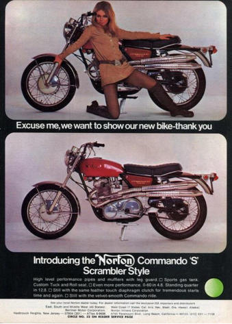
The ***** University test procedure for a Commando diaphragm spring is as
follows:
The friendly Gent in the Mech. Eng. Dept. places the spring and standard Commando
pressure plate in the Commando spring test jig as per the picture and places it beneath
the ram of the computer controlled load machine. The spring is in its FREE STATE
condition at the 0 deflection and load points - at the bottom left hand corner of the curve.
As the test machine applies load to the PRESSURE PLATE the spring starts to deflect
and with increasing load being applied it deflects to the deflection point marked 0.6
where the load reaches the MAXIMUM peak and for further deflection a reducing load is
required. For those who don’t believe this occurs you can ‘feel’ it occur as you deflect
the spring using the tool you use to fit the spring into the clutch and deflect the spring
through its flat state, especially if you have some Copperslip on the thread and under
the nut. With reducing load being applied the spring deflects through the SPRING FLAT
point at 1.0 deflection and continues to deflect with reducing load still being applied till it
reaches the MINIMUM peak at 1.4 deflection after which increasing load is again
required to deflect the spring further. Now this curve recorded by the test machine is the
one where the machine is applying load to deflect the spring at the pressure line/plate
BUT fitted into our clutches the spring is applying load TO THE pressure line / plate as it
tries to spring / deflect back to its original free state condition at the 0 load and 0
deflection points from well past the spring flat state condition that it was in when being
fitted into the clutch (with the correct tool) but with the tool removed it is stopped from
fully deflecting back to its free state condition by the plates and is thus applying load to
them. So the test machine is switched over and records the load the spring applies to it
as the spring deflects back from its 2.0 deflection point to its’ free state condition at 0
deflection and this gives us our CLAMP LOAD CURVE for that particular diaphragm
spring and pressure line diameter. This second set of results, with the spring deflecting
back from 2.0 to 0 will give slightly lower load values than the first curve where the test
machine deflected the spring from 0 to 2.0, due, just in case anyone is actually
interested, to hysteresis losses within the spring and frictional losses at the fulcrum
points and this effect is shown on the ‘Dyno Dave’ web page curve.
So let us pretend the 2.0 curve shown on page 4 is the CLAMP LOAD CURVE and
mark it so.
Now we want to obtain the RELEASE LOAD CURVE to determine the load we have to
apply to the release ring to free off the clutch and as it is we who to free off the clutch
are pushing the spring at the release ring towards its max deflection point we now get
the test machine to apply load TO the RELEASE RING to deflect the spring from 0
deflection to 2.0 deflection and record the results. This gives us a curve of similar shape
but only approximately 55% in load value to the CLAMP LOAD curve so draw this curve
and mark it RELEASE LOAD. At deflection point 0.6 release load = 0.7, at 1.0 = 0.55
and at 1.4 = 0.4 etc...
Just in case anyone does not understand why the release load should be lower - just
like me at one time, not having engaged my brain and remembered my 1st year
Mechanical Engineering classes from a great many years previously - I will TRY to
explain it as my friendly Laycock Eng. Gentleman explained it to me and then even I
remembered such things as moments about fixed points, levers etc..
27
Consider the diaphragm spring to be a lever with the outer edge of the diaphragm
spring being the fixed in position end of the lever. Let’s pretend it is an original Laycock
Eng. diaphragm spring applying approximately 380lbf. to the pressure line with the
clutch fully engaged. The pressure line is approximately 1 inch from the fixed outer edge
of the lever thus the spring is applying a turning moment ‘about’ the fixed outer edge of
the lever of 380 lbf. x 1 inch = 380 inch lb. To initially start to free off the clutch we have
to apply to the release ring an equal, but in the opposite direction, turning moment of
380 inch lb. ‘about’ the fixed outer edge of the lever but the edge of the release ring is
approximately 2 inches from the fixed outer edge of the lever and 380 inch lb divided by
2 inches = 190 lbf. Thus it is, mechanically, an approximately 2 to 1 ratio device.
In ‘normal’ Haussermann diaphragm spring clutches where the inner fulcrum point
(pressure line) is in its ‘normal’ ‘correct’ ’standard’ ‘usual’ position on the Belleville
spring this ratio is much greater, as in car clutches. In the earlier Villiers Starmaker
clutches it was an approximately 5-1 ratio according to ‘The Motor Cycle’ 21-2-1963
report which is also shown in the book ‘British 250 Racers’ pages 54/55. This
approximately 5 to 1 ratio should of allowed the high clamp loads of approximately 840
lb./f. and 700 lb./f., which the two different springs employed were designed to apply
when correctly set up in the single and twin friction plate Villiers Starmaker clutches,
with easy non-concentration-sapping clutch lever operation for the people using the
various editions of the motor with their different torque / power outputs (for trials,
scrambling and road racing use) IF the springs were correctly set up and the lift
mechanism correctly designed but I am NOT going to assume this was the case as both
may have been Villiers responsibility.
I was told Villiers initially failed to disclose to Laycock Engineering that the clutches
were to be run within an OBCC and oil / oil mist so Laycock Eng. designed them DRY
clutches employing either Ferodo RYZ or VM20 friction material (both of which are
shown on their data sheets to be DRY use only materials) and it was only when Villiers
reported the new clutches were slipping that Villiers first mentioned oil to Laycock Eng.
and the friction material was changed to sintered bronze so that when oil eventually
entered the dry clutches and upon reaching the friction surfaces resulting in slip the slip
quickly generated very high temperatures that - in theory - burnt off the oil leaving the
clutches once again - in theory – dry; eliminating the slip and would do so without
damaging the sintered bronze friction material (as was occurring with the original friction
material) and all without a MAJOR, EXPENSIVE, time and money consuming clutch
and motor redesign! I.E. the use of sintered bronze friction material was a bodge to
very cheaply and quickly get Villiers out of their deep doggy doo.
Mind you, I ‘heard’ from an ex NVT Gentleman the other day that Triumph had supplied
to the Trident clutch designer the torque value at the crank shaft with which to design
the clutch rather than the greater torque value at the slower rotating clutch / gearbox
input but that the designer (who was also probably a designer of car clutches which are
attached to the crank) had been very generous with the service factor he had employed
so they just got away with it.
I note on the Norman Hyde web site that various stronger springs are available for it to
increase Trident / BSA3 clutch torque capacity so I suspect the std. clutch could well be
‘minimal’ in torque capacity.
28
However, OUR Commando approximately 2 to 1 mechanical ratio is comparing both
‘push’ curves and takes no account of the slightly lower clamp load curve due to
hysteresis and frictional losses and when comparing the clamp and release load curves
for a STD. Commando clutch set up the release load is approximately 55% of the clamp
load value. I.E. if a spring inserted into your fully engaged Commando clutch were set
up to apply let’s say 300 lbf clamp load to the friction interfaces via the pressure line
then for you to start to free it off you have to apply 300 x 55% = 165 lbf to the release
ring (which REDUCES the further you pull the clutch lever as you drive the diaphragm
spring through its flat state). In an old coil spring clutch with coil springs applying 300
lbf. clamp load you would have to apply 300 lbf. to the pressure plate to start to free off
the clutch which would INCREASE the further you pulled the clutch lever as you
compressed the springs towards or even into their coil bound state and using the std.
BSA / Triumph / Norton existing lift mechanism and one hand you have to be a ‘REAL
MAN’ to do that a few times in a traffic jam, as on the later Commandos.
One UK belt system maker (NOT Mr Newby) once told a friend at a Stafford Show
in answer to a question that he could see no advantage to diaphragm spring
clutches. The friend was rather amazed at that U.K. belt system manufacturer’s
lack of clutch knowledge.
UNFORTUNATELY we never get anything for nothing in this life and in this case we
lose ‘freeing off’ lift in return for easier / lighter freeing off clutch lever action.
Explanation… In our old coil spring AMC clutch IF, with the clutch lever back to the bar,
the std. lift mechanism has moved the solid alloy pressure plate 0.080 inch then we also
get 0.080 inch lift at the outer edge of the pressure plate and within the clutch plate
interfaces which with say 6 friction plates giving 12 interfaces gives us approximately
0.0067 inch per interface which is perfectly adequate for good drag free freeing off;
assuming the plates are flat and not stuck together with oil, that is…! HOWEVER, with a
std. Commando clutch fitted IF the std. lift mechanism gave 0.080 inch lift at the release
ring it gives NO lift at the fixed outer edge of the diaphragm spring and only
approximately 0.040 inch lift at the pressure line which is approximately halfway
between the 2 points assuming the release ears do not bend (which they do), reducing
the lift at the pressure line even more and IF the pressure line were in its ‘normal’
‘correct’ ‘standard’ ‘usual’ position just outside the inner edge of the Belleville spring the
lift would be considerably less than half the lift given at the release ring and there is NO
WAY the clutch with 4 friction plates / 8 friction interfaces would ever free off using the
original lift mechanism or possibly any lift mechanism, not without possibly damaging
the Belleville spring…
Can everyone now guess why the pressure line is not in the ‘correct’ etc. position but
was moved on to the release ears / fingers further towards the release ring thus
increasing the lift at the friction interfaces? The greater lift allowing the use of 4 friction
plates / 8 interfaces giving a slower wear rate per plate and probably going some way to
meeting the friction materials’ heat spec and the load per engaging tooth on the centre
along with things I know little or nothing about but it reduced the clamp load to
approximately 380 lbf instead of the 800 ISH lbf it would be at the ‘correct’ ‘normal’ etc.
pressure line position. However, 380lbf. clamp load was far greater than ever used on
any previous Norton clutch, gave the dry clutch torque capacity required and the new-
fangled diaphragm spring gave very easy two finger clutch lever operation whilst
requiring NO MAJOR CHANGES to the original existing lift mechanism; thus saving a
major time and money consuming redesign for Norton /AMC for their cheapo 2 year
stop gap model Atlas Mk3 / Commando.
As far as I can ascertain Laycock Engineering had NOTHING to do with the
design / bodging of the Commando ‘clutch’.
29
30
11. THE CLUTCH LIFT MECHANISM
In his web page ‘Dyno Dave’ states, and I quote, ‘The Atlas actuator cam certainly has
more than adequate lifting range for a Commando clutch, and in fact the Commando
actuator cam gives more than double the lift needed to completely disengage the
clutch. This makes the ROD / cam ball free play adjustment of little concern in actual
use, with the Commando actuator arm’.
A couple of points possibly worth mentioning…..
1 The Commando clutch actuating cam (clutch operating lever 06-0715 in the parts
books) and the earlier Atlas / AMC one (04-0029) both give very similar lift at the clutch
for the same amount of clutch operating lever CABLE movement.
2. The Norton/AMC clutch and its lift mechanism were, I always understood, originally
designed to employ a handlebar clutch lever with a centre distance between the centre
of the lever pivot and the centre of the cable nipple of 7/8 inch. For Commando models
the std. (?) levers of the time and the later Lucas equipment employed levers with a
centre distance of 1 1/16 inch which resulted in a greater movement of the cable thus
moving the operating lever further; giving increased lift at the clutch.
I once did some testing. NOT laboratory type where measuring of the movement of
handlebar lever and clutch operating lever would be taken to determine exactly what
was happening but close enough for my needs at the time. However, I am incapable of
turning the adjuster back exactly 180 +/- 0.00 degrees by eye, which led to slightly
different readings on each of the 4 days I spent an hour or so in my cold garage taking
them in an attempt to get close repeatability by which time I said something akin to ‘sod
this for a game of soldiers’ and yet again retreated back into the house for a warm and
several cups of tea. But this fourth time, whilst slurping tea, I added the 4 sets of test
results together and averaged them out to give the results shown in the table below.
Repositioning of the dial indicator over the pressure line each time was probably within
+/- ½ mm or so. At each change of handlebar lever and clutch operating lever the cable
was totally disconnected and the adjuster reset to give zero play.
As different handlebar grips vary in diameter and clutch levers vary in shape both
effecting total lever movement along with the clutch operating levers probably varying a
tad, I suspect other people would obtain slightly different results.
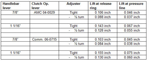
As the results show it was ONLY the change to a handlebar lever with a 1 1/16 centre
distance between the lever pivot point and the centre of the cables barrel nipple that
gave the increased lift required for the Commando clutch. (Nor does it give more than
twice the lift required to correctly free off the bronze clutch with its 10 friction
interfaces).
The 7/8 inch centres lever and 04-0029 clutch operating lever combination giving 0.088
inch lift at the release ring (and pressure plate on a Dommy or Atlas) gives more than
adequate lift of 0.007 inch per interface for say an Atlas clutch with 12 DRY friction
interfaces but in my experience using this system giving 0.037 inch (ISH) lift at the
pressure line with a 4 friction plate Commando clutch giving 8 interfaces and 0.0045
inch per interface using both the DON 112 solid fibre and later Surflex friction plates
(which SOME refer to as solid fibre although they actually have an aluminium alloy core)
good drag free disengagement is only achieved with NO oil around, once the friction
plates are bedded in, the plates are totally flat and the adjuster adjustment is spot on or
a tad under being backed off 1/2 a turn. Personally for road use I would not consider
using the combination UNLESS it were in conjunction with a belt driven dry 3 friction
plate diaphragm spring slightly narrower clutch which I sometimes cobble together for
friends 650s and 500s etc. with their lower clutch torque capacity requirement.
(The reason for the aluminium core to the Surflex friction plates is simply to stop the 25
inner driving ears from dropping (shearing) off. The earlier solid fibre DON 112 material
was asbestos based and gave shear strength of around 9,000 lb / sq inch but more
modern in theory safer NON asbestos moulded materials have much lower shear
strength so the core is there to stop the ears from dropping off in use! NOT LONG ago a
friend sent me some supposed Commando friction plates to look at. They were greyish
in colour and looked as if they were made from wetted and sat on cardboard in some
Far Eastern back street workshop! They were also semi flexible and the 25 teeth came
NO WHERE NEAR fitting a clutch centre and would have required hours of careful filing
to get them to correctly fit the involute tooth form. I had them shear tested by my friendly
University ……..Shear strength was less than 3,000 lb per sq inch. Wonder how long
the teeth stay on the plates if used?? I heard one main Norton dealer took one look at a
set and banned them from his shop….)
With the 1 1/16 lever moving the spring further than with a 7/8 lever, which = more work
being done, doesn’t this make the clutch lever harder to operate over the same total
handlebar lever hand movement? If you have really heavy clutch lever action with your
AMC / Norton coil spring clutch it could be worth checking which clutch lever you have
fitted and if 1 1/16 inch centres try fitting one of 7/8 inch centres to see if it makes lever
action more to your liking - but it would be a tad difficult on my ES2 as it is fitted with
Lucas switchgear levers. When I first built it from bits I wanted 12 volt electrics and easy
to operate bright winkers for use when changing lanes in the rain at night on motorways
etc. along with a real front light unit (Wipac Quadoptic with a real light-giving H4 bulb)
and a rear lamp with at least two bulbs for both rear and brake lights to allow for
vibration failure and a reasonably easy to hit in an emergency horn button on both
switches. I never did fit the brand new ex BSA Saudi police bike Maserati twin air horns
which could simply, by flicking a switch, give one tone or the two tone police sound...
ideal for use when behind the brain dead driving the children to school while nattering
away on their mobile!! Every motor cyclist should have a set fitted if only on safety
grounds so even the deaf can hear you and the blind brain dead you just know is NOT
going to see you and pull out directly in front of you…..!! Really must fit the other set to
the car one day soon…..
31
As far as I am aware there were two changes made to convert the AMC 04-0029
operating lever into the later Commando 06-0715 version. The first being to shorten the
outside of the end where the cable is attached to stop the lever fouling the inspection
cover or something as it approached the increased full lift point given by the increased
cable pull of the 1 1/16 inch centres handlebar lever and the second, I WAS TOLD,
was a very slight change to the radius in which the roller ‘works’ so as to end up with a
more constant change in lift over the total movement whilst giving the same total clutch
lift as given by the earlier 04-0029 operating lever and 1 1/16 lever which my testing
showed gave more than adequate lift of 0.055 - 0.060 inch at the pressure line to
enable a Commando clutch to free off correctly when required. If you want even lighter
clutch lever operation so windage alone operates it convert your gearbox inner and
outer covers etc to employ the far more expensive to produce earlier Norton worm gear
lift mechanism, a friends so-fitted 650SS has an easy one finger coil spring clutch lever
and nor did the chain driven clutch suffer from slip as he normally thrashed the motor
before olde age finally hit him a couple of years ago. Last time I saw the bike it had
covered 80,000 miles without the motor being touched apart from normal servicing.
However he does know to use a straight thin oil and to fill the chain case till oil is just
touching the chain and cleans the clutch down to remove any oil working into it every
10,000 miles or so. His Primary Chain life has always amazed me with the crap
lubrication of the chain. But he only used Renold chain marked ‘MADE IN ENGLAND’
and these days Renold chain made for use on, so I was told, Harrier aircraft.
32
12. A DEVELOPMENT ATLAS MK3 / COMMANDO ‘CLUTCH’.
I suspect, I repeat SUSPECT, that had the fitting of a triplex chain arrangement to the
Atlas clutch as fitted to a ‘development’ bike worked anything like correctly then that is
what we would of ended up with on the Atlas Mk3 / Commando….along with its
ridiculously heavy clutch lever action which Mr Hele told me reached abound 300lbf and
my back of fag packet calculations show it would not be far off 300 lbf with the lever
back to the bar.
Unfortunately the Norton /AMC clutch was originally designed such that the centre line
of the singlex chain ran directly over the centre line of the rollers supporting the basket
so with the clutch fully freed off the basket stayed roughly in the same place BUT the
centre line of a triplex chain (or belt) fitted to the clutch overhangs the rollers supporting
the basket and when trying to smoothly engage the clutch when starting away the
torque in the over hanging chain or belt pulls the back end of the basket around forcing
the clutch friction interfaces into the pressure plate engaging the clutch more than
required as you are trying to slip the clutch to slowly engage it. With an open primary
you can actually watch the basket pulling over as the clutch just starts to bite. Anyone
want to guess why Triumph later so called ‘clutches’ were fitted with thrust bearings to
locate the basket in place (not that many owners ever maintain them) or why BSA
dished their triplex clutch chain sprocket? On a road bike it would have been totally
unsuitable and it wasn’t that great on our Atlas’t when part of the original British made
belt system as it normally resulted in the rider, being 50 yards down on the leaders into
the first bend OR the clutch engaging too much causing the motor to ‘bog down’ ……
Removing bump starts took so much ‘fun’ and skill out of racing. On a road bike the
engagement characteristics pulling away from a standstill would not, in my opinion,
have been remotely acceptable even for a two year stop gap model. Plus, when it
happens, it means the engine and clutch pulleys are no longer correctly aligned which in
turn puts most of the load on only a small portion of the overall triplex chain or belt width
which is NOT a clever thing to do and in my opinion is one reason for premature chain
and belt failures on Triumph twins etc. using the std. coil spring type ‘clutch’, especially
as a great many Triumph owners do not replace the thrust washers locating the basket
in place when they are worn which in turn (because the two pulleys are even less
parallel all the time) forces a belt to thrust hard into the engine pulley outer guide plate
all the time which can result in quick wear to the edge of the belt. This is especially so if
the guide plate is not of the correct shape. (Guide plates have specifications - not that
you would think so, looking at some guide plates).
One British system maker (NOT Mr Newby) apparently thinks it is a belt problem when
a belt thrusts into a guide plate and suffers edge wear. It is a system problem that
results in a belt edge wear problem and it would occur no matter whose belt were fitted!
If the engine pulley has correctly made inner and outer flanges and the pulleys are
made and set up correctly, any ‘neoprene’ or polyurethane belt will wander back and
forth between the guide plates / flanges making light contact with them in service with
NO belt edge wear problem. With a loose belt and high torque conditions, non parallel
pulleys can result in the belt riding up on to the guide plate and self-destructing -
especially if the guide plate is not to spec... Running a chain loose on incorrectly aligned
sprockets doesn’t do it much good either…
33
Naturally, the majority of owners will blame the chain or belt manufacturer’s product for
a failure (especially if the chain has come through the chain case!!), rather than
determining the real cause… just as I did with our first belt system for a few months till I
noticed the belt not correctly fitting the incorrectly toothed clutch pulley as shown in ‘the
books’ and thus began my belt learning curve which is still continuing over 30 years
later, along with all the many other learning curves.
The development Norton / AMC triplex chained clutch was later ‘found’ shoved under a
bench and was used by Mr Negus on his privately entered Commando which, averaging
over 100mph, finished second to John and Charlie Williams on a Honda 4 (an unofficial
works bike?) in the 1973 Spa 24 hour race.
I ‘heard’ the Norton works race team manager would not talk to the ‘privateers’ working
in the factory for a while afterwards probably for managing to build a Commando motor
and gearbox that stayed as one working lump for a whole 24 hour race! Which I
understand was beyond the factory team…!
The ‘Negus’ motor I was told had previously completed a 6 hour race only receiving a
quick check over before entering the 24 hour race and one ‘Behind the Picture’ article in
a motor cycle weekly was headed ‘Employee beats Factory’. Bet that went down like a
lead balloon with ‘some’ people. Wonder if the privateers shoved up photocopies
around the factory just to ‘wind up’ the factory team?
The riders for the 1973 Spa 24 hour race were Peter Davies and Peter Lovell.
Did any Norton works Commando motors actually stay together long enough to
complete a 24 hour race? I was very recently told by an ex Norton / NVT Gentleman
that when both the Negus and factory Commandos competed together in endurance
racing there was only one instance of a factory bike finishing in front of Mr Negus’s
private entry bike. I also ‘heard’ the Mr Negus bike was in a lower state of tune than the
factory bikes and that the 1973 Spa race was the only instance of a British bike of the
time averaging over 100 mph in a 24 hour endurance race, not that I have checked to
confirm it to be fact. I have no doubt someone will do so! Apparently the timing side
suspension unit came adrift from the swinging arm towards the end of the race making
handling even more and I quote Mr Lovell “interesting”. See later in the Atlas Mk3 /
Commando frame problem / fiasco section for one possible reason why it came adrift.
34
13. SETTING UP THE DIAPHRAGM SPRING IN A FULLY ENGAGED CLUTCH
For a diaphragm spring clutch employing a spring with Degressive-Negative-
Progressive load / deflection characteristics, a designer will design a motor vehicle
clutch such that when new and with the clutch fully engaged the deflection point of the
spring will be around midway between the spring flat point and the MAX load peak, the
diaphragm spring having been correctly designed and manufactured to give
(approximately) the required clamp load at this deflection point.
For this exercise let us assume it is at the 0.8 deflection point on our curve so draw a
vertical line at the 0.8 deflection point intersecting both the clamp and release load
curves. At this 0.8 deflection point the original (correctly designed and manufactured)
750 spring the DRY clutch was originally designed to employ applied approximately
380lb./f. clamp load and the last batch manufactured by Laycock Eng. for later
Commando production applied approximately 550 lb./f. clamp load which of course
required a lot more ‘grunt’ from the rider to free off…
There are several good reasons for selecting this ‘around the 0.8 deflection point as the
new clutch fully engaged deflection point.
ONE of them is that in a car etc. clutch they have an axial compression device
sandwiched between the two friction material surfaces on the friction plate and
something like 3 to 4 inches of the foot pedal clutch engaging movement is taken up as
the diaphragm spring compresses the axial compression device which results in a
slowly increasing clamp load being applied to the friction interfaces providing a gradual
clutch engagement characteristic unlike a std. Commando clutch which is basically an
on or off switch (unless there is oil on the friction interfaces!). Thus the diaphragm
spring is deflected a lot further in a car clutch than on a Commando clutch and I
understand even if set up at around the 0.8 position with the clutch fully engaged with
the car clutch pedal to the floor the spring is sometimes deflected into the area where
the loads start to rise again past the 1.4 deflection point.
Another reason is that as clutch plate wear occurs then with the clutch fully engaged the
deflection point of the spring is going to slowly work its way back from the 0.8 deflection
point towards its free state condition at the 0 deflection point but note that as it does so
the clamp load initially rises to the max peak value before eventually falling back to its
original value. Thus with a ‘correctly’ set up original Commando Laycock Eng. spring
clutch the first approximately 0.045 inch of total wear in the friction interfaces increases
the clamp load from approximately 380 lbf. to approximately 430 lbf. (increasing clutch
torque capacity) and it is only after a further approx. 0.045 inch of wear that the clamp
load (and thus clutch torque capacity) have reduced back to their original 380lbf. value
and it is only with even further wear that clamp load and thus clutch torque capacity will
decrease below their original value unlike in our old coil spring clutches where any wear
reduced the clamp load / clutch torque capacity and the springs require to be tightened
to compensate. (For the LAST version of the Laycock Eng. spring the total wear
required before clamp load actually reduced below its original value is approximately
0.095 inch).
35
In your car clutch this total wear movement, where clutch torque capacity has NOT
reduced below its original value, was / is now (?) roughly equal to the amount of friction
material wear that had / has (?) to take place before the rivets attaching car clutch
friction material to its backing plate become exposed and the friction plate required
replacement.
A probably uninteresting tale… On the original development Hillman Imp women drivers
loved the light clutch lever action of the diaphragm spring clutch especially the way it
became easier to operate the further they depressed the pedal BUT they disliked the
way the pedal sprang back with increasing force as they engaged the clutch and the
diaphragm spring was changed to one giving a depressive-horizontal-progressive load
characteristic giving a more constant ‘feel’ to the clutch pedal when operated.
36
14. A little WARNING…
Some ‘people’ tell / told owners they can lighten Commando clutch lever action by increasing
the ‘stack height’ of the clutch plates by fitting a thicker pressure plate. Whilst this is correct
(because it moves the deflection point of the spring with the clutch fully engaged towards or
past the spring flat state thus reducing the initial and further release load) as far as I am
aware they have totally neglected to inform people of the major ramification of doing so,
probably because they themselves are / were totally unaware of the consequence.
One Company started flogging 0.050 inch thicker Commando pressure plates to the public for
just this purpose many years ago and when I phoned them shortly after, asking ‘Can you tell
me what effect fitting one has on clutch torque capacity?’ even after a couple of minutes of
hearing background discussion they could only eventually tell me that they did not think it did.
Their answer to my question SHOULD have been.…
’If you fit one of our 50 thou thicker pressure plates into a std. correctly set up Commando
clutch you will reduce the release load by something like 20-30%, depending upon the height
over thickness (h/t) ratio of the spring fitted and the shape of its load / deflection curve, thus
making clutch lever action lighter BUT you also reduce the clutch fully engaged clamp load by
something like 20-30% and thus you also reduce the clutch fully engaged torque capacity by
something like 20-30% making the clutch EVEN more prone to slip problems… Sir’.
You NEVER get anything for nothing in this life.
Check it for yourself. Look at your Haussermann tippex-ed clamp and release load curve.
With a spring set up ‘correctly’ with new friction plates fitted the clutch fully engaged deflection
point of the spring will be at let’s say the 0.8 deflection point where you previously drew a
vertical line. By fitting a 0.050 inch thicker pressure plate you would be setting the clutch fully
engaged deflection point of the spring at or just past the 1.0 deflection point. As you can see
by looking at the clamp and release load curves at this new deflection point you have
successfully reduced not only the initial release load but also the clutch fully engaged clamp
load and thus the clutch torque capacity.
With the 550 lbf. clamp load / heavy clutch lever action of the late Laycock spring and oil on
the friction interfaces the clutch in theory torque capacity is still no-where near great enough if
the clutch is not, in theory, to slip when anything like max torque is put through it so, in my
opinion, it would be rather silly to reduce the clutch torque capacity to obtain a lighter
operated clutch lever unless you are never going to use much of the motors available torque
or want an even lower value torque limiting device / ‘clutch’.
HOWEVER…
IF the chain system has been replaced with a dry running belt system and the clutch is
running DRY, the approximately 550 lbf. given by the last Laycock Eng. spring gives you a
clutch with FAR TOOO MUCH torque capacity when fully engaged (unless you add a second
motor). So to reduce the clutch torque capacity to the - in theory - required level, rather than
wasting your time trying to find an original as rare as hens teeth early 750 spring which many
people threw away thinking they were knackered and causing their clutch slip (replacing them
with later thicker edition ones that increased the clamp load and made clutch lever action
heavier, not that many I suspect realised this is what they were actually doing), you can alter
the deflection point of your diaphragm spring with the clutch fully engaged to reduce the
clamp load (reducing the torque capacity of the clutch) which in turn reduces the release load.
37
For the last new late Laycock Eng. spring I tested and then set up to do this for a
Triumph T140 clutch employing 4 DRY Surflex friction plates whilst giving an easy two
finger operated clutch lever, I added an extra 0.060 inch to the ‘stack height’ with the
use of a thicker pressure plate which with the clutch fully disengaged still did not drive
the spring to the MIN load point at full lift.
However with the other various diaphragm springs employed in Commando clutches
over the years, and I doubt many owners have any idea as to which version diaphragm
spring they have fitted, you might only require anything between 0.060 to say 0.020 inch
to do this… and, in some cases, with the earlier versions of the spring fitting a 0.050
inch thicker pressure plate MAY well reduce the dry clutch torque capacity to below that
which is required if clutch slip with the dry clutch fully engaged is not, in theory, to occur.
38
15. DIFFERENT COMMANDO DIAPHRAGM SPRING COMPARISON
Following is a little Commando diaphragm spring comparison table.
I will also include my test results for the NON Laycock spring now available of which I
tested ten in July 08 using my test set up and for those wondering…which includes a
new FULLY calibrated load cell and digital readout device as it was more convenient
and quicker to do my own testing although I now have to draw the curves rather than
having them magically appear on my computer from the friend at the University but
drawing curves keeps me out of trouble and is a restful pursuit! All the results shown
(apart from the T140) show the clutch fully engaged clamp and initial release load
recorded at the 0.8 deflection point midway between the MAX peak load and the
SPRING FLAT point. I.E. they are approximately what you would get by simply
swapping THESE PARTICULAR diaphragm springs in the same ‘correctly’ set up fully
engaged Commando clutch. Even within a production run batch of diaphragm springs
the load / deflection characteristics can vary by up to 5%.
All APPROXIMATE values. Release loads shown are at the release ring / clutch push
rod.
Looking at those release load figures, guess why early 750 models had nice light clutch
lever action while later model Commandos cause / caused wrist and hand ache to
those who ride / rode their bikes in stop start traffic rather than from one end of a
motorway to the other without touching the clutch lever?
The later Commando models just like T140s, early 750 Ducati and Laverdas etc. were a
MANS bike with a MANS clutch lever operation! (Did not Triumph once advertise T140s
as a MANS bike?)
I will point out that the first batch of non Laycock springs I bought many years ago (and
had tested at ***** University) were thinner than the ones now available and gave loads
about mid-way between the original and last Laycock Eng. springs giving reasonable
clutch lever action. HOWEVER the manufacturer is, I understand, now denying they
ever made such springs and that their drawings only show one version. Wonder where
the batch I bought came from? Especially as they had exactly the same release ring as
the ones available these days from the same manufacturer! (There is a tale there as to
why the spring was changed but I won’t go into it as it was really all my fault that it was
changed to the one now available after I pointed out to a certain Gentleman that the
spring did NOT give the same load characteristics as the last version of springs
employed on late 750 and all 820 clutches and sent him copies of the load deflection
curves).
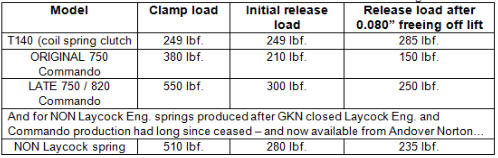
39
When I ordered 10 new springs not long ago I had ASSUMED (will I never learn to
never ASSUME?) they would be as the earlier ones I had bought and had tested a few
years previously. Had I wanted ones similar to the late Laycock ones I would have
saved my money and taken them from the 40 or so new late Laycock ones still sitting in
my loft.
There was a very BIG pile of very cheap ones in a Birmingham emporium shortly after
NVT went to the wall which I understood had been destined for use in a future Triumph
diaphragm spring clutch and at the time I did not know about there being different
springs….but they were a bargain…There also was, at Shenstone, a big steel storage
bin full of new Commando clutch centres that some ‘brain’ had then had tapered so they
would fit the std. Triumph gearbox main shaft thus I saw, for the only time in my life, a
tapered spline or splined taper! Wonder how much that pile of scrap cost to
manufacture and who the ‘brain’ was for the splined taper?
An early Commando road test said, firing a full broadside at UK bike manufacturers,
from memory so possibly not word perfect… ’I find it incredible that such a delightfully
light and positive clutch could have been ignored by motor cycle manufactures for so
long before being introduced on the Commando’. So what was fitted to the earlier
Villiers Starmaker motors? By ‘light he was referring to clutch lever action and certainly
NOT their static and rotating weight!!
Personally, the FIRST time I pulled the clutch lever on a nearly new early production
750 Commando the owner had brought over to the I.O.M. at Manx G.P. time, I turned to
him and asked “OK so who is the clever ******* who has disconnected the *******
clutch?” He laughed and replied “funny but most people ask that question”.
It was a very QUICK lesson as to how clutch lever action could and should be.
On another Gents similar Commando, the clutch did NOT suffer from slip drag or heavy
lever action during a ‘slow’ canter around the TT course with the two of us on board as
we stayed within the speed limits and whilst slow - with our combined bulk and the std.
front brake (?) - if you believe ‘stayed within’ there is little hope for you. The lap would
most certainly have been a bit quicker had a real front brake been fitted but its use in
anger might have caused the fork bottoms to shear. You think it has not happened?
Note how the later disc fork bottoms were oval in section……
Mr J. Williams stated in his early 1950s 7R and E95 design / development note book
that he had visited Dunlop to look at their disc brake development so I suspect disc
brakes were something else he wasn’t allowed to develop on ‘his’ AMC factory race
bikes leaving it for his son Peter to do on the Arter brothers AMC race bikes many years
later.
Perhaps had Mr J. Williams developed disc brakes on his race bikes British production
bikes would have had them fitted many years before they eventually did.
Reading the Mr Geoff Duke book the other day I note he tried at around the same time
to have Girling develop motor cycle disc brakes but apparently Girling management
refused, stating disc brakes will never be used on motor cycles or something equally as
‘clever’ and short sighted.
40
Clearly either the oil level was correct within the Commando OBCC or the few
thousands of miles it had covered from new had not allowed enough oil to reach enough
of the friction interfaces to result in slip as the bike with two lumps on it was ‘spiritedly
used’ (road test speak for well screwed?) up and out of Ramsey and on to the Mountain
Mile and just about everywhere else. Fortunately neither the frame main spine or down
tubes failed which could of proved an interesting experience for us so I guess the frame
was the modified design version. As I have never seen in print an account of the initial
frame problems I will give my version later which is based on ‘tales’ heard from people
‘involved’.
One Gent I knew, during a MGP practice lap in the late 60s, had the front forks and
head stock part company from his frame on his ****** G50 as he went up through
Sarah’s Cottage – which, I understood, was rather an exciting and possibly interesting
experience for him! The following day a white van driven by a certain Gentleman arrived
in the I.O.M. containing a similar bike for the Gent to use and those involved were sworn
to secrecy. It may well have been the bike on which the driver of the van had lapped at
over 100mph in an earlier TT. A friend who was ‘spannering’ for the rider and staying in
our usual ‘digs’ had told me all about the frame failure hours before he was sworn to
secrecy.
41
16. THE VASTLY OVER WEIGHT BRONZE PLATED GEARBOX BREAKING (?)
FLYWHEEL (?) CLUTCH (?) FITTED TO LATER COMMANDO MODELS
When I first described the bronze plated ‘clutch’ / ‘gear box flywheel’ to the Laycock
Eng. Chief Clutch Designer / Engineering Director as he was at the time the phone went
silent and after he had done a quick calculation he said “But surely the clutch suffers
slip and drag problems due to oil working its way in via the bearing and the slots in the
diaphragm spring. The Gentleman then asked what was what was the mechanism
employed to ensure the friction interfaces freed off instantly without drag whenever
required and I replied that there was no such mechanism. I do not think he was at all
impressed with the lump as a clutch AND for his calculation I later learnt he had
assumed a higher clamp load of 800 odd lbf. as used on one of his earlier Starmaker
clutch designs rather than the 550 lbf. the late Commando springs actually gave at their
unique / bodged pressure line.
Is it true that with the bronze plated lump Norton won outright the inter factory (BSA-
Triumph-Norton) trophy for the heaviest static and rotating weight ‘clutch’ / gearbox
breaking(?) unbalanced(?) gearbox mounted flywheel(?) ever fitted to a British motor
cycle?
As I remember things, it didn’t take long after the introduction of the lighter (than the
bronze plated lump) 750 Commando clutch before much lighter alloy clutch baskets and
centres became available for those who wanted to reduce rotating weight… clearly
some enterprising soul knew our clutches were supposed to possess the lightest
rotating weight reasonably possible rather than the heaviest and saw a ready-made
market for such things! New batches didn’t stay on the shelf very long in a friends shop
although I do wonder if in using them for road use the average owner noticed even the
slightest difference apart from to their bank balance.
Required clutch torque capacity for an 820 bronze plated prize winning (?) ‘clutch’ /
gearbox flywheel /etc…
Max crank torque = 55 ft lb. x primary ratio of 57 / 26 = 120ft lb. x safety factor of x 2 =
240 ft lb. Greater than the 750 which in turn was greater than required for the Atlas not
that the gearbox changed…
In theory clutch torque capacity.
There are 5 friction plates = 10 interfaces. Effective radius of interfaces = approximately
0.21 ft. Assuming the person responsible for this version of the ‘clutch’ did NOT know
the spring had been changed several times by then and had assumed the original
Norton test results showing a clamp load of around 380 lbf. still applied and why should
he or she have known it had changed? Norton never changed their part number for the
spring, had they even changed the Laycock Eng. spring reference number on their own
overall clutch assembly drawing?
42
Rule of thumb C of F for design purposes for sintered bronze is DRY 0.3. WET 0.08-
0.06 and of using 0.08 the retired Laycock Gentleman told me he was not that optimistic
and had used 0.06 for all his many wet ‘bronze’ clutch design calculations throughout
his working life.. But let’s be optimistic and use 0.08. (And 0.06 just for the hell of it).
Thus the in theory torque capacity of the ’clutch’ would be…
DRY 10 x 0.021 x 380 x 0.30 = 239.4 ft lb
WET 10 x 0.021 x 380 x 0.08 = 64 ft lb
WET 10 x 0.021 x 380 x 0.06 = 48 ft lb
One reference page on the web somewhere suggests 0.13 as the C of F for greasy
sintered bronze so if we assume the black gunge (burnt off oil) that ends up on the
friction surfaces within these clutches (due to the heat build-up in the clutch during slip
conditions burning off the oil causing the slip) to give this sort of C of F value the in
theory torque capacity is still a lot lower than required.
BLACK ‘GUNGE’. 10 x 0.21 x 380 x 0.13 = 103 ft lb.
As the required clutch torque capacity is 240 ft lb it was (torque capacity-wise) clearly a
very well designed DRY clutch for an 820 Commando IF employing the original
diaphragm spring which would have given nice light easy clutch lever operation. For a
late 750 there is a tad too much clutch torque capacity but with easy two finger clutch
lever operation would anyone care? (Very few people apparently having thought about
its weight and possible ramifications on gearbox reliability).
Even using the wrist and hand exercising clamp load of approx 550 lbf given by the later
spring we still get an in theory clutch torque capacity lower than that required if slip is
not to occur with oil on the friction interfaces …assuming the person riding the bike is
using the throttle when, for example, riding away from all the stone sober lemonade
drinkers at ‘The Creg’ and ‘screwing it on’ up towards ‘Kates’ and ‘Kepple Gate’ with a
friend on the rear showing everyone how quickly and noisily a Commando can
disappear out of sight round the corner!! Assuming that they do NOT met some total
brain dead coming the other way on the wrong side of the road as they enter or exit
‘Kates’ OR their crank does not decide to become a 4 piece version on the way up to
‘Kates’ breaking across the drive side outer 90 thou radius which is not exactly an
unknown occurrence thanks to even more lack of quality control at Norton /AMC / NVT.
(See later).
Using the last Laycock Eng. Spring with its approx 550 lbf clamp load (and heavy clutch
lever operation) if using a dry belt we get a DRY in theory clutch torque capacity of…….
10 interfaces x 0.21 ft effective radius x 550 lbf clamp load x 0.3 C of F = 346ft lb.
which is far too great so either find an as rare as hens teeth early 750 spring OR fit a
thicker pressure plate to reduce the clamp load / torque capacity and giving lighter
clutch lever action OR at your own risk add a second motor and go sprinting.
43
I very much suspect the change to sintered bronze friction material was forced upon
Norton as the stronger diaphragm springs that had been employed by that time had not
cured the 750 slip problem (while introducing ridiculously heavy lever action) and
because they did not have the time and money available to increase clamp load further
and introduce the hydraulic operating system that would be required to operate the
clutch OR to redesign the clutch etc. etc..
My money would be on a meeting being held to discuss the problem with no one
coming up with any ideas till a very brave or stupid ex Villiers person stuck their head
above the proverbial parapet and said something like ’I know it’s a really silly idea but
when we had a similar problem on our Starmaker clutches many years ago we changed
to sintered bronze so that when oil entered the clutch causing slip to occur the very
quick heat build-up within the friction interfaces due to the slip burnt off the oil causing
the slip leaving the clutch in theory dry again but without damaging the sintered bronze
as it did the original moulded friction material’.
Wonder if anyone from management (mismanagement?) screamed ‘Eureka’ and ran
around naked just like Archimedes did all those years ago…so the tale goes anyway...
The temperature spec given for the 06-1339 Don International asbestos based solid
fibre friction plates is max continuous 100C / max intermittent 300C whilst for Ferodo
sintered metal SM1 material for example it is continuous 300C / max intermittent 500C.
I assume it was at the same time that they changed the clutch centre material to one
that could be induction hardened to reduce the problem of the steel bronze faced plates
notching the centres’ splines.
Irrelevant – but interesting – anecdotes… probably of no interest what so ever, but’ I’ll
include them.
Slipping the clutch also generates very high temperatures.
One friend on his return many years ago from a Classic MGP and, I think, being first
British 350 to finish told me that with the 4 speed box fitted to his 7R with its narrow-ish
power band and having to slip the clutch to keep the motor in the power band / ‘on the
megga’ he could have practiced the section from Ramsey up to just past The Guthrie
Memorial at night from the light of the glowing clutch! I think he was joking but luckily the
neoprene Goodyear Super Torque Pd belt I had used for the diaphragm spring clutch
belt system hardened slightly with heat rather than going all soft and sticky as one
system maker once told Norton Owners Club members neoprene belts do due to heat
(Roadholder magazine Issue 130 Nov/Dec86 Page7) passing on yet more
‘misinformation’?
The rider also reported the lighter clutch lever action to be worth 20 plus seconds a lap
due to simply changing gear to keep the motor in the power band rather than thinking
‘my hand aches, I’ll give it a rest and not change gear now but let the revs build up on
their own’ thus costing a few seconds every time it occurred as the motor laboured
away out of the power band / ‘off the megga’.
44
45
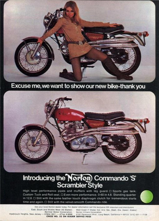
It isn’t only engine tuning that can help bikes lap faster… No primary chain oil on the
rear tyre helps as well I believe!
Many decades ago on an MG being raced at Le Mans the heat build-up between the
clutch friction material and the metal mating surfaces as gear changing took place down
that long straight was enough to very slightly melt and move the metal mating surfaces
a tiny amount but enough to later measure under a microscope and knowing the revs at
which gear changing occurred to determine the time it took for full engagement to take
place. Clearly someone at Laycock wanted to know! See, we did used to have some
real research Engineers in this country!
Of course it may well be that on a Commando with the correct type, grade and amount
of oil within the OBCC slip may not occur for many thousands of miles use even if using
the throttle against the stop some of the time, especially if you fitted a sealed for life
bearing into the back of the clutch / flywheel to stop oil entering it via the bearing and
somehow stopped oil from entering via the slots in the diaphragm spring.
A hint given in the Commando Service Notes book is to use SAE 10-30 Castrolite in the
OBCC which was recommended for OBCC use in my youth and in some books (my
A65 factory workshop manual for example). I understand Castrolite is no longer
available in the UK and it was suggested to me by several oil technical people I talked
with to now use as thin a ‘straight’ engine oil as possible.
Somewhere I still have a few ‘new’ gallon cans of what must be by now vintage straight
10 and 20 engine oil I bought specifically for OBCC use many decades ago. Morris
Lubricants in the UK can supply suitable straight 20 oil. Friction inhibitors in the oil are
not a good idea for our clutches either as a friend found out 40 plus years ago as he
added some then new-fangled Moly Slip to the engine (and thus clutch) oil on his
Enfield Constellation one dinner time at work. And with our brains disengaged we
watched him do it! Took him a seriously long time to get home after work thus proving
the friction reducing properties of Moly Slip and that evening he had to flush out the
engine several times and strip and clean his clutch so he could get to work the next day!
Many years ago one British bike spares emporium dealer friend bought a pile of second
hand ex USA Commando clutches and I took on the job of stripping them for any good
hardened centres that could go into stock but really to see if there were any signs
proving that the tale of slip due to oil was fact. At a guess there were 30 ish ‘fibre’ plate
and 15 ish ‘bronze’ plate clutches. I found that there were moderate signs of heat build-
up on all the ‘fibre’ clutch plain steel plates with ALL of the friction plates (Don
International 112 solid fibre asbestos based material) oil impregnated and seriously
glazed but that every plain steel plate removed from the ‘bronze’ lumps was seriously
‘blued up’ due to heat and that everything was coated in ‘black gunge’ sticking all the
plates together. I ended up using a wood chisel to separate the plates.
46
Those bronze plate ‘clutches’ had done a lot of slipping (and dragging) in their U.S.A.
life. Of course the riders may not have noticed it occurring or even thought of it as
unusual. Many especially those who overfilled their OBCC and actually used the throttle
probably regarded a std. Commando clutch slipping when fully engaged as ‘normal’ and
that it was time to spend Sunday morning stripping it out to wash everything in petrol to
remove the oil or black ‘gunge’ before overfilling the OBCC again to the oil level plug
hole instead of the CORRECT level (750/850 Workshop Manual. Section K8. IGNORE
Section K9!!). Of course some could have thought the slip problem was the result of
their engine tuning ‘skills’! But they would always get you home.
Personally AS A DESIGN I think the Atlas Mk3 / Commando (Haussermann) clutch was
the best fitted to any late British Twin. AS A DESIGN. As stated previously it works
VERY well possessing ALL the basic qualities shown much earlier whilst weighing
around 6½ lb. (or less with an alloy centre for splined main shafts only and hard
anodised to 0.002 inch depth as are my pulleys) and being run dry with a belt on T120s
T140s, A65s, G50s etc. etc., even when racing and scrambling and BIG bore A65s
(840cc..A10 crank and B44 pistons) lugging a sidecar through thick mud put LOTS of
grunt through the clutch and the neoprene belt has never given a problem either - but I
probably played it very safe and supplied a 40mm wide belt system.
One road test for a UK monthly conducted using a friend’s 6T fitted dry diaphragm
spring clutch belt system and a QPD (Bob Oswald) designed electric start system (as
fitted to his own T140 and Commando for decades) described them as and I quote ‘A
revelation’ and compared to what Triumph ended up with I suspect ‘a revelation’ is
probably spot on…… To start with the starter uses a bendix and not the crappy sprag.
The starter drives a bull ring mounted on the rear of the clutch basket and the belt
drives the engine…..
Funny how the later produced Nortons ended up with a somewhat similar electric
start system to the QPD one but I suppose if one borrows QPDs (Mr Oswald’s) all
belt driven electric start Commando to study first… which Mr Oswald told me was
never returned.
Personally I had advised Mr Oswald not to touch the fellow US Gentleman with
even a very long barge pole but he did not heed my advice. I understand from Mr
Oswald that the QPD website shows a video of the Gentleman giving the
Commando a look over before ‘borrowing’ it… I believe Mr Oswald still has the
registration documentation for the bike so if anyone reading this now has that
bike you know where you can obtain the documentation but it would not surprise
me if you were asked to pay for the bike!!!
Just in case it is of interest to bronze plate clutch owners: In one so called ‘classic’ bike
magazine there was once an article on the subject and one of the points it made was
that if the plates were worn 0.002 inch undersize they should be replaced. I did wonder
if the writer was being paid by Norton dealers. I measured several new bronze plates
and all were 0.002 inch down on the size stated as correct in the magazine.
47
Now I suspect Norton dealers around the World made a very profitable killing
moving ancient stock after the article BUT the same applies to the bronze plate
clutch as it does to the earlier fibre plate clutch……. IF the spring is ‘correctly’ set up
initial wear INCREASES the clamp (and release) load and thus clutch torque capacity
and for the last spring used for Commando production, assuming the diaphragm spring
is correctly set up in the first place, the clamp load curve shows that it requires
approximately 0.095 inch of total wear within the friction interfaces BEFORE the clamp
load and thus clutch torque capacity reduce back to their original values. I.E if we
assume say 0.015” total wear of the nice CORRECTLY hard cold rolled and polished
steel inter plates (IF genuine or Surflex ones) and 0.080” total wear of the bronze faces
that is 0.016” wear per bronze plate and IF, under normal road use, you manage to ever
get enough engines to stay together long enough to give the clutch use required to ever
reach 0.016 inch wear per bronze plate you could just fit an extra plain plate into the
back of the clutch or thicker pressure plate to restore the diaphragm spring fully
engaged deflection point back to its original point so your great grandsons or
granddaughters or their offspring can continue the quest to try to wear all the bronze
from the friction plates (Assuming they can operate the clutch lever that is.). Of course
similar will also apply to clutches using non bronze friction material plates.
48
17. THE DIFFERENCE IN THE VARIOUS LAYCOCK ENG. COMMANDO SPRINGS
IF you have made it this far you most certainly DESERVE to know the easily found
difference between the 4 different Laycock Eng. Commando springs. NOTE. All
diaphragm spring load values given are when employing a STD Commando pressure
plate with the STD Commando pressure line diameter……unless stated otherwise.
The difference is in spring thickness and a CUBE LAW applies to it. I.E. The original
750 Commando spring was approximately 0.075 inch thick and if correctly set up
applied approximately 380lbf. clamp load. The last springs used for Commando
production were approximately 0.084 inch thick and applied approximately 550 lbf.
clamp load. So, IF you simply changed the thickness of the original spring from 0.075 to
0.084 inch whilst managing to retain an identical spring height over thickness (h/t) ratio
it would in theory apply, at the same spring deflection point, approximately 380lbf. x
84/75 x 84/75 x 84/75 = 534 lbf. which is close to the 550 lbf. which I stated was the
approximately clamp load given by the last spring used for CommandIo production. The
h/t ratio of the 0.075 and 0.084 inch thick Laycock springs being a bit different which
might explain the few Lbf difference due to the different curve shapes but have not
investigated it and don’t care either. Even between springs made as part of the same
batch I am told you can get variations in their load characteristics of anything up to 5%.
The EN47 designation or whatever it is these days steel strip they are made from will
have a tolerance of around 0.001 inch and may vary in thickness a tad from one end of
the BIG roll of strip to the other end that they are made from as could the weight of the
shot used and / or the time it is applied for to peen the springs to increase their fatigue
life. Cannot say I have noticed any shot peening to the non Laycock Eng. Commando
springs now available.
The Laycock Engineering drawing I have for their 6.294 inch diameter spring range
shows there were 8 different versions (Ref 10 – 80) with clamp loads ranging from 750
lbf. to 1280 lbf., h/t ratios of 1.8 to 2.18 and spring thicknesses ranging from 0.073 to
0.0845 inch. Change note 14 dated 11-11-71 changes thickness tolerance from 0.001”
to 0.0015” for all editions. The drawing shows outer and inner fulcrums as being 6.156
and 5.280 inch diameter. I suspect the load values given on the drawing are for these
fulcrum points. The springs I found in Commando clutches and have had tested were
approximately 0.075, 0.078/9, 0.080/1, 0.082 and 0.084 inch thick. Some were probably
at their max or min tolerance thickness and in theory were the same ref. spring. I doubt
that even if I asked very nicely Andover Norton would tell me what their clutch
assembly drawings show regarding the ref numbers of the springs employed and the
dates from which each new edition was employed. I was told the spring fitted to
production rotary bikes was Ref 70 which is the one shown to be giving a clamp load of
1280 lb./f. (at the Laycock fulcrum point).
A friend has retrospectively fitted a few early Rotaries with the F1 Sports hydraulic
clutch operating system and many owners I was told suggest it is needed.
49
The drawing change notes also state that different material specs were used for some
ref. springs although what the changes were I have no idea and nor am I going to
bother to try to find out. I believe the original Starmaker springs were part of this 6.294
inch diameter range, one being approximately 0.073 inch thick and the other
approximately 0.077 inch thick which are I believe the Ref 10 and 20 ones shown on the
drawing as the thicknesses and clamp loads shown are those quoted to me in a letter
from the designer of the single and twin friction plate versions of the Starmaker
clutches.
50
18. A COUPLE OF POINTS
1. In his web pages ‘Dyno Dave’ talks about the release fingers being inserted into the
release ring via offset piercings in the release ring and how some release ears ‘work’
before others. Bet the waffle impressed many people reading it. Exactly why anyone
would be interested in what the release ears are doing with respect to each other and
the pressure plate is I fear either beyond me or unimportant. However, JUST in case it
is of interest to anyone the ONLY reason for the 40 thou offset to the piercings in the
Laycock Eng. (Haussermann) release ring is as follows: The piercings in the release
ring require to be larger than the hardened ends of the release ears so as to fit them
into the release ring. If the piercings were all in line then the release ring would vibrate
on the ears resulting in VERY QUICK WEAR AND FAILURE along with generating
MORE noise than any NON totally deaf car owner could stand. (I was told to ask any
Hillman Imp owner club member with a few hundred thousand miles use on their
original Laycock clutch diaphragm spring and release ring if I did not believe…). So the
Haussermann brothers in Germany offset the piercings so the release ears clamped on
the release ring eradicating the noise generation and quick wear problems over the
‘normal’ life of a car. They also, so I was told, patented the idea. However just to confirm
my thoughts on the subject were something like correct I phoned my friendly retired
Chief Clutch Designer and asked him about the effect on lift of the release ears being
offset to each other and he said he had never really thought about it but that he would
go away and have a think. Overnight he must have had a think because the following
morning he phoned saying it was of no real importance as far as he was concerned.
Mind you his clutch designs would have had the pressure line in the ‘normal’, ‘standard’,
‘usual’, ‘correct’ position on the Belleville spring and NOT on the release ears. Anyway it
is irrelevant now as the NON Laycock spring that has been available from Andover
Norton for decades has a different release ring design and all the release ears work
together in unison even if they do bend a bit in use!
2. Some people have told me that the diaphragm spring never changed quoting the fact
that Norton retained the same part number for it over the years. Personally for a VERY
long time I could not understand why various clutches gave such ridiculously different
clutch lever actions till one evening I was ‘amusing’ myself for a few hours (yes, I do
need help / therapy / to get a life!) ‘playing’ with a pile of new / second hand Commando
springs and a micrometer, ‘wondering’ when I noticed thickness variations. My first
thought was that the material was 2mm / 0.079 inch with a tolerance of +/- 0.005 inch
but as it was only about 10pm and cut off time in those days for talking to the by then
retired Laycock Eng. Gentleman was 11pm I phoned asking if it made a difference to
the load characteristics and I then learnt all about the cube law relating to diaphragm
spring thickness.
Shortly after I had first contacted Laycock Engineering I tried to obtain a copy of the
Commando spring drawing but was told they had, and I quote, ‘all just been filed in a big
skip a few days previously’ due to GKN being in the process of closing down Laycock
Engineering. I believe the clutch side was flogged off to L.U.K. Yet another British short
term profit and no long term future closure? Luckily just like many of the BSA drawings
ordered to be skipped and burnt which were ‘diverted’ and saved (some of which I
understand are still waiting to be sorted and catalogued, some even old linen drawings)
a copy of the Laycock Eng. drawing ‘appeared’ one day a few years later via the post in
an unmarked brown envelope from where I cannot possibly say.
51
I SUSPECT what happened was that as Norton had a clutch slip problem, which of
course like many of the other Commando problems they had they did NOT publicise,
problems such as porous heads, loose valve guides, different length con rods (or was
that in Atlas times only?), soft cams, advance retard units that didn’t (not for very long
anyway) etc someone in purchasing was told to get the next batch of diaphragm springs
made by Laycock Eng. 10-15% stronger to increase the clamp load and thus the
amount of torque the fully engaged clutch would transmit before slip occurred. However
as this did NOT solve the slip problem the ‘trick’ was performed a couple more times
further increasing the clamp load / clutch torque capacity each time but still not enough
to ensure the fully engaged clutch would NOT suffer from slip with oil on the friction
interfaces IF the owner applied enough torque to it that is …..
I assume the some owners knew that slip should NOT occur with a fully engaged clutch
and that the odd one or two even wrote in complaining.
Car owners would have done so in vast numbers especially if the slip had
occurred on holiday touring Devon and Cornwall etc. trying and failing to get up
those 1 in 5 hills with the wife and kids in the car and a caravan on the back! Mind
you most if not all car owners would have had the sense and balls to return their
cars very quickly to the dealers as being unfit for purpose demanding their
money back and RIGHTLY so which would have made the manufacturer very
quickly sort out the problem!
Trouble was that the increase in clamp load was not enough to increase clutch torque
capacity to eradicate the slip problem due to oil and possibly the annoying pain in the
butt moaning owners so the process was repeated several times eventually raising
clamp load from approximately 380 lb./f. to approximately 550 lb./f. (still no-where near
enough to make the clutch a correctly designed, torque capacity wise, wet clutch) and
the grunt required to operate the lever rose from easy two finger operation to
ridiculously heavy. I.E. the heavy clutch lever action of the later production models was
simply down to the use of ‘stronger’ diaphragm springs, or with earlier clutches by fitting
a new (later edition stronger spring) thinking the old one was knackered and causing the
slip problems, assuming the clutch is correctly set up along with the cable in good
condition, lubricated and correctly routed. Even nylon lined cables require lubricating as
a friend found out the other day after fitting a brand new one……
52
19. MORE WAFFLE…
Whilst totally irrelevant…when I originally phoned Laycock Eng. to pick brains the first
Gent I spoke with said something like ’Strewth, years without anyone mentioning Rotary
Norton and now a second phone call in a week’ (He later transferred me to the
Engineering Director / Chief clutch designer). Naturally I asked who the first call was
from as I had thoughts it might be from a certain UK belt system maker (NOT Mr
Newby) trying to learn something about clutches but it had actually been from the
Norton rotary race shop asking if ‘stronger’ springs were available.
Was it really clutch slip that resulted in the early rotary race bikes slowing down
towards the end of races that I watched happening on TV?
Shortly after whilst phoning Mr Hele at Norton at Shenstone to yet again pick at his
memory banks from his Domiracer development days I asked if the race shop had a
clutch slip problem and after a bit of a silence as he composed his reply (something
both he and Mr Hopwood would do) he very carefully replied that they did not have the
problem with the rotary production bikes but that it should be remembered the race
shop motors shoved out a bit more of everything so they may well have a problem.
I took his answer as a yes.
There are ex NVT employees I have spoken with who feel that restricting Mr Hele to the
production models only was one of the bigger management cock ups.
Apparently few people realise that the TT winning rotary race bike of the early 1990s
employed a dry running std. off the shelf 8mm pitch Gates PolyChain belt on the
primary. I assume this was to allow a lighter dry clutch close to the gearbox main
bearing and to also give a few more H.P at the rear wheel which would have previously
been wasted in heating up the World if chain or silent chain were employed especially at
the high primary drive linear speeds used most of the time.
Was any dyno testing done to record power at the rear wheel before and after fitting a
belt primary? I have asked the question in the past but have yet to receive an
answer…….
Could it be that it was the use of the Gates belt that was partly responsible for that TT
win? NOT that Gates ever to my knowledge used it in any of their publicity bumph unlike
Uniroyal in the USA who did in the late 70s when their new non trapezoidal tooth form
HTD belts were being used on for example Harleys setting speed records at Bonneville
and on other bikes and cars setting sprint records etc. with the belts outlasting the
previous chain and trapezoidal belt systems many times over.
I did hear whilst talking to the rotary race shop that they had initially tried another belt
after lots of long phone calls telling them what they should be doing from a UK belt
system maker using that particular trapezoidal tooth form belt but that failures occurred
very quickly during testing at a local race circuit. I was told that failure occurred before
completing a lap. When I then said “I bet the teeth stripped” the race shop person I was
talking with said “How the hell do you know?” I replied that it was what I would have
expected to happen with that belt due to high torque unless they had gone for a wide
belt of say 40/50mm width.
53
However one ex NVT Gent I was talking with not long ago whilst confirming the quick
belt failures said he thought it was the result of incorrect belt tension and if under
tensioned the belt could very well have jumped pulley teeth (ratcheting) and stripped a
block of teeth or snapped the belt especially if there was any lubrication on the belt and
pulleys but I know which cause my money would be on. Trapezoidal tooth form belts are
more prone to tooth jump (ratcheting) than HTD tooth form belts…having just been
looking at some test results comparing the torque required to induce ratcheting to occur
with same pitch trapezoidal and HTD tooth form belts. The HTD tooth form belts
required approximately 3 times more torque to be applied before ratcheting occurred
than did the trapezoidal tooth form belts.
Anyway Norton eventually found a belt that worked. I was also TOLD that the same
standard off the shelf Poly Chain belt stayed on that rotary race bike for the whole years
racing including the TT without any problems at all although I heard recently from a
Gentleman who ‘was there’ that the engine was well knackered after the TT but he
added “so were those of the bikes finishing behind us”.
A rotary race Norton (the actual TT winning one?) can or could be seen in the National
Motor Cycle Museum complete with a 30mm wide Gates Poly Chain belt (well it was
when I measured it although I had been told the race bike used a 25mm wide belt) but I
doubt many Norton visitors have even noticed the belt drive let alone wondered why
Norton didn’t use the belt one UK system maker told the World in his adverts ‘was the
strongest and highest revving in the World’ till the UK Advertising Standards Authority
told him to change it that is. From then on it was only in his opinion that it was the
strongest and highest revving……. (The ASA. adjudication date was 26-09-01 but they
only hold adjudications on their computer for 5 years. I guess if you asked nicely they
would provide you with a copy of the adjudication if you wish to read it.
‘Dyno Dave’ (and others) sell seal kits for the gearbox main shafts so they must believe
it is oil working its way down the centre of the main shaft into the clutch that causes the
slip problem rather than the oil within the OBCC required to in theory if not in practice to
correctly lubricate the chain. Wonder why it is that Norton manuals give over filling the
OBCC as one reason for slip problems and not oil reaching the clutch via the main
shaft?
I must admit I have never noticed the problem with our dry clutches, not that I actually
looked because we never suffered from slip problems although I have heard of it
occurring with dry belt systems but I suspect it could be the end result of another
problem if oil is migrating down the main shaft and causing the slip problem.
54
I wonder for example …
1. How many owners polish their AMC gearbox inspection cover and block off
the small gearbox breather hole so the box then breaths through the main shaft
taking oil with it?
Yes that tiny hole is the breather hole, real motorcyclists having sealed around the cable
at its entry point to stop any ingress of water either into the box or on to the inner of the
cable along with sealing the end of the spare cable attached to the cable in use at the
handle bar, which ensures the cable in use will never fail… Sod’s Law being what it is
the cable in use only fails miles away from home within hours or days of removing the
spare to re-lube it or something as I once found out. A friend recently came back from a
German trip on his T140E fitted with a dry diaphragm spring clutch belt system and the
new USA made solid non asbestos fibre friction material plates I had water jet profiled
out of sheet and fitted for him to try (for myself and the friction material manufacturer)
were as dry as a bone upon his return….just as expected and, just for those wondering,
I have a program on disc for correctly water jet profiling the friction plate involute tooth
form thanks to a certain Chief Designer I have never actually met who very kindly forgot
to pass the bill on to his company accounts dept. which was very kind of him especially
as it was not a standard slide fit profile and several a few thou different each time
profiles were tried ONCE I eventually found a correctly toothed clutch centre to try them
on… some British made centres were oversize, others undersize and some even had
tapered splines so a friction plate that fitted one end would not fit on the other end! I
eventually found and bought a large pile of correctly made ones in a Birmingham motor
cycle emporium…. they had been made in Taiwan decades previously.
2. How many owners overfill the gearbox and / or use the wrong oil which could
result in oil passing through the main shaft more easily?
3. Wonder how many are using the incorrect diameter push rod? I SUSPECT the
pushrod was originally 15/64 inch in diameter with the hole in the main shaft drilled ¼
inch. (15/64 inch = 0.2344 inch). Mind you I could and probably am wrong because I
have not bothered checking trying to find ancient drawings. I ‘believe’ the pushrod
drawing now show it to be 6mm diameter (0.2362 inch). However when I collected
together all my new and second hand AMC and Commando main shafts the hole size
varied and with some a lump of ¼ inch rod would ‘fall’ through. Mind you I did find one
new one where there is no hole all the way through, the drilling from each end not
having met in the middle with others meeting in the middle with probably less accuracy
than the guys did when boring the tunnel under the English channel from each end and
eventually meeting and with a couple a 6mm pushrod would not easily push through.
Guess they were non genuine shafts?
Thus, with some holes being oversize and people blocking off breather holes and
overfilling gearboxes etc I am not surprised some people have oil working its
way down the main shaft but TO DATE I have not noticed it occurring so I have
never had to look for a cause.
55
Personally since reading about seal kits I have thought about using a single sided
sealed bearing on the main shaft so that the oil churned up in the gear case can
lubricate the bearing but not easily work through to fall on the main shaft and pushrod
and I may try it when I next build or rebuild a box, a sealed one side bearing being only
slightly more expensive than a non-sealed version. A smear of grease on the lift
mechanism and pushrod should suffice for lubrication? I understand some people have
been using a BMW valve stem seal for many years but I have no idea as to its part
number or price.
Some people say that the diaphragm springs become weaker over time and should be
changed… So how many miles / years do car ones last? Just about forever is the
answer unless VERY seriously overheated although I am told that over the years their
load characteristics could reduce by up to 5%. I ‘suspect’ such people are unaware that
there were different springs giving different load / deflection characteristics. IN FACT in
the N.O.C. Commando Service Notes Book it states that if you stand on the release ring
your weight will deflect the spring through its flat state and out the other side. This is
correct for the ORIGINAL spring IF you weigh 17 stone but it isn’t for the later ones and
it took myself and wife / better half together to get it to occur which was no surprise
once I had had a later edition spring tested and found it gave a max peak clamp load of
around 600lbf. (using a std. Commando pressure plate) thus requiring a MINIMUM of
600 x 55% = 330 lb / 24 stone on the release ring to push the spring through and past
the max peak point.
I will very happily accept and even pay the postage for all the supposed weak
Commando springs thrown into corners / lobbed into drawers etc. so I can use
them for friends dry belt drive clutches for their 650 / 500 Triumphs, BSAs,
Nortons, 7Rs, G50s etc. which require even lower clamp loads than the original
750 Commando …unless I cobble together 3 friction plate clutches for them.
56
19. SOME REALLY ‘CLEVER’ IDEAS FOR COMMANDO CLUTCHES.
The first has been covered earlier ….the use of thicker pressure plates to make clutch
lever action lighter without informing people of the major ramification of reducing the
clutch torque capacity increasing the risk of clutch slip problems. (See section 14 page
37).
Another ‘clever’ idea around at one time decades ago was to remove some of the
release ears to make clutch lever action lighter which it would do but only because the
remaining release ears would bend more between the release ring and the pressure line
rather than deflecting the Belleville spring as much and with the reduced lift at the
pressure line drag could become even more of a problem. Not that I have been stupid
enough to try it to find out. If the std. diaphragm springs did not need 18 release ears to
work something like correctly or 12 wider ones as on the diaphragm springs I
sometimes use then I suspect the manufacturers would have used less. As I stated
earlier I ‘heard’ in 2007 that one major clutch manufacturer was looking at ways to
reduce the lift lost due to bending in the release fingers. Since then I have seen release
ears with ridges pressed into them along their length which would reduce their
bending….
Some people electroplate (chrome/nickel) their diaphragm springs (some even
electroplate their frames and swinging arms)…. During the process of electroplating,
Hydrogen gas may be absorbed through the surface of the material of the spring or
frame / swinging arm leading to the material becoming brittle resulting in possible
premature failure. I know it as hydrogen embrittlement.
If you look at your diaphragm spring you will note that some edges have a radius. Well,
they should have. The Laycock Eng. springs have them. This is because of the very
high stress concentrations that occur at these points. Thus the radius reduces the risks
of premature spring failure so to increase it with electroplating would seem pretty stupid.
Electroplating may possibly even alter the springs load deflection characteristics? I
suspect it will because with a spring in its free state condition one outer surface is in
compression whilst the other is in tension with the steel in the centre in a neutral state
but as you deflect the spring towards its flat state the compressed surface becomes
under tension and the surface under tension becomes under compression and the
chrome surface layer will I SUSPECT have an effect. However I have better things to do
in my retirement such as sweet nothing than test a spring, have it chromed and then
retest it to see if the chroming makes much of a difference to its load characteristics.
Some people electroplated scramble frames and a friend says thanks very much every
time he has to repair them or make totally new frames to replace them as it is
sometimes cheaper to make new than repair, the repairs required sometimes being
extensive. Some owners then have the new frames plated…. Some people even have
their road frames that have already seen who knows what abuse over the last 40 or 50
years plated and they fail as well, some even do so without the help of plating! Mind you
if you saw some of the frame ‘repairs’ done by some other people that the friend has to
correct it is amazing that more owners do not die on our roads and race tracks. Nickel
plating also causes hydrogen embrittlement. Wonder what galvanised frames look like?
57
After many years of not doing so I eventually read my ‘Belleville Springs Company’ disc
spring users guide book and found it states…
‘’DO NOT ELECTROPLATE DISC SPRINGS. During the process of electroplating
hydrogen gas may be absorbed through the surfaces of the disc spring, which in turn
may lead to the spring becoming brittle. Whilst it is possible that a subsequent heat
treatment may relieve this condition, our experience has shown this to be unreliable’.
I wonder how many electroplated frames or swinging arms ever had a correct heat
treatment cycle applied? Especially the frames and swinging arms some people have
made over the years using thin 18g tube. It is no surprise to me or a frame maker friend
that some new ‘classic’ race frames made these days are suffering failure after only a
few meetings use.
A couple of years ago one friend borrowed a pile of test gear from work and spent a day
at Mallory Park trying to determine why a new ‘classic’ racing frame had failed at points
original Reynold made ones never failed at.
My first reaction to hearing about the failure was that someone had used the wrong
gauge tubing or incorrectly welded the tubing weakening it or incorrectly bent them…
having at one time asked a couple of frame makers how they did such things and
received different contradictory answers. Std. Manx swinging arms were 1½ inch 12g
with a further lump of 14g shoved up the ends of the tapered down to 1 ¼ inch legs
(which by then were around 11g size tube) before they were ‘trapped’ and flattened.
Even the 3(?) 18g Manx frames made by Reynolds for Mr Beart were I believe only
made on the basis that they would be cut up on safety grounds after a couple of
seasons racing and the same may of applied to the original works Domiracer 18g
frames and I know of one that was still around in 2008 because I borrowed it to
photograph and draw up to check it against the AMC / Norton drawing office drawing
that had ‘come my way’. On the dated ‘1961 AMC / Norton’ drawing the rear chain
would of cut straight through a cross member had the frame had it in the position
shown. As it was it was a couple of inches higher on the frame.
People tend to forget, till it is too late, how many must have died or been injured racing
due to incorrect material use or inappropriate welding.
For info, Manx frames were made of 1 ¼ inch O.D. 16g Reynolds 531. Inters 14g CDS
(Cold Drawn Seamless) A grade. Dommys etc. 14g CDS B grade (UNLESS Reynolds
ran out of 14g CDS in which case Manx 16g 531 was sometimes employed till new CDS
stock came in but that I think was only in the early days of bolt up wideline production.
One friend has a couple of these lighter frames and sif - bronze welded new Manx rear
ends on).
People tend to forget those who have been injured or died due to frames etc failing
….Florian Camathias who died at Brands Hatch in 1965 readily springs to mind, mainly
because I was there at the time.
58
HAUSSERMANN
MANY thanks to ‘Haussermann’ for putting onto the web such an excellent technical
document.
Also, MANY thanks to the retired Laycock Eng. Gentleman for his hours of repeating
bits of technical info to me till I finally understand - which he ensures by making me
explain things back to him till he is happy I really do understand.
If ONLY the so called teachers in my youth both at school and later college had done
the same instead of going on to the next bit leaving myself and much of the class not
understanding the last bit and at a total loss from that point on.
Mind you in those days, steam engines, piston engine aircraft and of course motor
cycles, smoking and boozing along with the opposite sex were much more interesting…
AN APOLOGY.
One Senior ex-NVT Gentleman who read this in its original form many years ago to
obtain his approval prior to it going on the web made several comments to me but I lost
interest in putting it on the web at that time and have now only revived it a great many
years later simply to please a friend.
One comment he made was that it was FAR too long and I TOTALLY AND
UTTERLY AGREE as I am sure you do but I am not going to waste some or most
of what is left of my life changing it now.
Since then I have added other sections just in case they might interest someone. The
other comment was that I was very critical of some of the people working at Norton /
NVT who were trying to do their best with little or nothing in the way of money and
development time to do it.
The Gentleman is correct and any such comments should have been directed at the
decades of British company owners, British company ‘owning’ accountants (NOT how I
normally spell it) and British mismanagements along with Unions and Governments who
had successfully reduced most of British industry to the state AMC were in by the time
the Atlas Mk3 was introduced with their (typical British?) lack of proper investment and
‘short term profit and no long term future’ thinking over the many proceeding decades
and even now. To those few probably very conscientious people who were still at
Norton trying to do their best against all the odds and hoping like so many in what was
left of British industry in those days and later and even now that retirement would come
before redundancy (and that the Company had NOT raided their pension fund reducing
it to zero) you have my DEEPEST sympathy.
Many is the time in my later working years I said, sometimes even beneath my breath,
‘boll***s’ to (mis)management and did my job to the best of my limited ability thinking
that’s how I would like it to be done if I were the end user with my life and that of others
depended upon the radar guided anti- missile system working correctly as several tons
of sea skimming anti-ship missile was heading my way at whatever Mach speed it is
they do these days but that was just me being bloody minded and not a ‘team player’!
59
Personally I was always surprised AMC actually sold any bikes with all the bits that
escaped the factory over the back wall or through the front gate. “Psssst, want a new
650SS head or how about a G50 one? A crank? New frame? New un-machined
magnesium hubs or would you prefer fully machined? New rods?” ‘Tis amazing what
one could find in ex AMC employees sheds or under floor boards…. if one
looked……..
Under one bench beneath a carpet I once found a pile of as cast magnesium G50/7R
hubs……!
One friend who bought probably the last Manx produced at AMC tells me he knows an
ex-AMC employee with a beautiful complete 650SS that cost him NOTHING and I
believe him. So how do you nick a frame? The gentleman either walked it out through
the main gate bold as brass or he had a mate on the gate that day. Another method I
suspect was to get a friend in the post dept. to pack and address items to you at
home. In those days a ‘borrowed’ from AMC new competition mag apparently cost £5
and a set of Roadholders - including yokes and headlamp shell - cost £20… so a
friend told me the other day.
A STATEMENT.
A couple of people in this World associated with motor cycles apparently
wonder why I dislike them.
It really is very simple to understand. For some reason I seriously dislike people
who pass on ‘misinformation’ to others especially when the ‘misinformation’
could - and probably does - influence the buying decisions of those believing
the ‘misinformation’ to be fact.
Many years ago one actually phoned me asking that very question. I lost my ‘cool’ (not
difficult in my diabetic olde age) and told him at great length as he was paying for the
phone call. I was told another such person actually ran up to Bob Oswald of QPD at a
Norton meet in the USA asking if he knew me / why I disliked him and this was before
Bob had even finished parking his camper, which could have been a dangerous thing
to do as Bobs’ foot could have easily hit the throttle…by mistake? I heard all about it a
few days later. It apparently greatly amused one of Mr Oswald’s sons accompanying
him and many years later Bob Oswald still laughs as he yet again recounts the tale to
me as we talk …phone calls to the US only being 3p a minute these days rather than
the £1 a minute they cost me to phone New York in 1965.
I also very seriously dislike people who place technical articles or advice on the web,
in club magazines, web forum sites etc. without having the decency or brains to at
least try to ensure that what they have written is technically correct BEFORE the
article or advice is submitted for publication or placed on the web, preferably by having
it checked by someone who actually knows something about the subject.
If I can go to the trouble of doing so then so can others. Doesn’t mean this is
100% correct but at least a lot of effort has been made to try to ensure it is.
My pet hate for many years has been one British belt system maker, mainly
because I have met so many people spouting his ‘misinformation’ assuming
they are spouting facts!
Of course my hate for the U.K. lying unemployable incompetent politicians
knows no bounds and grows daily to eventually replace all the black matter in
the Universe!!.
60
A FEW SUBJECTS THAT MAY BE OF INTEREST.
22. The Commando / Atlas Mk3 early frame ‘problem’.
Firstly, I was asked to state that the Reynolds Tube Company did not offer advice
to customers UNLESS it was specifically requested by the customer.
(‘REYNOLDS’ = the tube and frame etc. manufacturers. ‘RENOLD’ = the chain
manufacturer).
The tale as I heard it…..
The Commando frame had been quickly ‘designed’ in house by Norton and Reynolds
were contracted to manufacture them. The Reynolds sales dept. probably handing the
Norton produced drawings straight on to the production dept. who simply followed
them… the customer is never wrong and if you follow the customers drawings and
things do then go wrong it is not your fault but that of the customer plus one can make
more profit correcting the faults for the customer which serves the customer right for
thinking they knew what they were doing in the first place and not first seeking advice
from experts.
Something like 100 (so I was told) Commandos were cobbled together, crated up, lifted
on to lorries and a short while later loaded on to a ship. Upon reaching America they
were lifted out of the ship and placed on to trucks. At the distributors however they were
apparently lobbed off the back of the trucks to the ground a few feet below (6 ft?). Upon
opening the crates (or what was left of them?) it was found that some main spine tubes
had failed where the front gusset plate from the headstock ended. On page 142 of Mr
Bacons book ‘Restoring Norton Twins’ is a frame drawing showing the original gusset
plate ‘design’ along with the front tank support bracket and steering stop mounted on
the front down tubes at a point of high stress where the down tubes would, so I was
told, also fail. On the same page is a picture of the modified frame. There is a photo of a
failed spine and one of a section through the gusset plate welding shown in Mr
Bradbury’s excellent book ‘The Racing Motorcycle’ Vol. 2. Page 147.
Back in the UK the proverbial hit the fan with those responsible telling people that their
calculations had not shown a problem… not our fault …must be Reynolds fault due to
their welding etc…
Its known as having Teflon shoulders in the UK M.O.D. and defence industry as projects
run seriously over time, vastly over budget and when finally delivered probably don’t
work anything like correctly either or the project gets cancelled before completion after
spending a fortune of tax payers money and here I am remembering A.E.W as just one
example. (See Google ‘BAe Nimrod AEW3’ for SOME of the tale).
So Reynolds had the welds examined, which is why there is a picture showing one in Mr
Bradbury’s book. I suspect Mr Sprayson has a great many other pictures showing
perfectly good welds.
61
At Reynolds I believe a (well attended by the work force?) test took place as they
dropped an Atlas Mk3 / Commando from a crane to replicate American truck unloading
practice??.
The people responsible at Norton suggested employing thicker heavier 14g or 12g tube
as a cure for the spine problem. At around the same time Reynolds were actually asked
for their input and I believe a Reynolds employee who knew ‘a little bit’ about tubular
frame design and construction having built a few successful ones in his time for motor
cycles etc. became involved and suggested removing the gusset plate and triangulating
the head stock with a tube from the bottom of the headstock to a long way back along
the main spine tube and transferring the tank support brackets to the new tube along
with moving the steering stop on to the headstock.(1953 swinging arm Gold Star frames
had a similar triangulation arrangement so such ideas were nothing new…see page 43
of the book ‘Goldie’ by Mr Golland or a parts book for a sketch). Apparently some
people in the motor cycle industry would invite a ‘Reynold Gentleman’ to visit them for a
drink and on the drawing board would be a new frame drawing which they would be
invited ’to look at so they could spot and point out the ‘deliberate errors’ Some designers
knew their limitations… those later at Norton clearly did NOT.
On test on the Belgian ‘cobbles’ pave test course (at M.I.R.A.?) an original 16g spine
frame failed after approximately 23 laps and the Norton-suggested 12g frame failed
after around 120 laps with the “suggested by Reynolds’” 16g version of the frame going
round and round for several hundred laps without failing till they gave up and sent it
‘scrambling’ in an attempt to induce a failure but once again failed to do so! Some of
you will be delighted to know that this is the version used on later Commandos.
Once again might I suggest owners do NOT read ‘The Worlds Straightest Commando’
web pages which may apply to the Italian made frames rather than the Reynolds-made
ones (?).
Never did get the story behind the Italian made Commando frame saga as the person I
asked who I ‘felt’ would know it declined to tell as he mentioned possible legal
repercussions if he were to do so. I did hear the tale (from Reynold people) that when
Reynolds were contracted to check and correct many of the Italian made frames they
made more profit per frame than they had in making a frame themselves in the first
place.
If the idea was to reduce frame prices by going to Italy I suspect it very seriously back
fired. Is it only the Italian made frames where the T.S rear suspension unit mounting
point is 6mm further out on the frame than on the swinging arm? I simply do not know
how friends owning them never noticed it till I phoned asking them to check their frames
were the same as on my ex-police Mk2A (and the brand new frame a friend in the trade
bought for me very cheaply in case it was needed)… the error stands out like a sore
thumb when viewing a bike from the rear as the T.S. suspension unit is noticeably not
vertical. It was amusing hearing their screams of ‘Oh S*** my frame must be bent’ etc…
62
One Gentleman who restored the odd Commando for customers over the years put a
large area washer on the T.S. swinging arm fixing point to stop the suspension unit
working off of the rubber bush and swinging arm whilst the bike is in use. Did someone
cock up the frame drawings changing them to metric for the Italians or was it the original
Norton frame or swinging arm drawings that were wrong? The big top tube on Italian
frames are a Metric O.D. size. The Reynolds ones an Imperial O.D. size.
I was told not long ago by a Gentleman still involved in the motor cycle trade who knows
such things that the Italian frame maker made - and still make - very good frames…”but
not at the price Norton wanted to pay”.
I heard an Italian made frame was, ex-factory, approximately 2/3 the price of one made
by Reynolds but I will not divulge the prices I was given. I was also told the Italian
Company found they could not produce the number of frames required by Norton per
month and that Reynolds were again contracted to help out.
I was informed by Mr Lovell (one of the riders) that the Richard Negus privately entered
Commando that finished second to the Works (?) Honda 4 in the 1973 Spa 24 hour race
had the timing side suspension unit come off the swinging arm close to the end of the
race which made things more exciting / interesting. Was it, I wonder, one of those
frames with the T.S. suspension unit 6mm further out on the frame than on the swinging
arm?
63
23. Clutch basket / clutch centre and clutch plate spline wear.
IN my youth, trying to be helpful, I started to take a 7R clutch apart and received ‘a bit’
of a boll****ing from the ex AMC race mechanic I was trying to learn from at the time.
Being someone who would pass on knowledge if he thought it would not be a total
waste of effort doing so he then proceeded to explain the reason for the boll****ing
which was that I had not checked to ensure the individual plates, basket and centre
were marked so that the plates could be replaced in EXACTLY the same order and
position in the basket and on the centre as they had been removed. He explained that
baskets, centres and plates are at best made to ‘commercial’ machining tolerances and
that even if you put new plates into a new clutch for every spline / ear in theory
engaging with the basket and centre probably only one or two of them per plate will
initially ‘engage’ fully and take the entire load. These then wear themselves AND the
bits they are engaging with till further splines / ears also engage and this continues till
all are eventually fully engaging and the load per ear is considerably reduced reducing
future wear to a minimum. To take all the plates out without marking everything so they
can be replaced exactly as removed results in the whole wear process starting all over
again and it is this that causes a lot (most?) of the wear / notching found in the splines /
ears of clutch baskets / centres and plates. It made sense to me and I now explain to
friends why the basket, centre and clutch plates of the clutch I have cobbled together for
them are all marked but as to whether they take any notice…
64

24. Four piece Dominator and Commando crankshafts.
In the late 60s my Dommy began emitting noises very much like seriously knackered
big ends which was a pain in the butt as I had just had the crank reground. Being on
‘holiday’ in ‘The Island’ for the Manx GP doing a bit of race bike polishing and
marshalling (up on ‘The Creg’ to ‘Bungalow Bridge’ section where really brave or stupid
souls fight the wind, horizontal rain and sleet, sheep and slugs marching across the wet
concrete floors of marshal huts etc. to marshal, especially when up there before dawn
breaks and the roads are closed in my younger days when early morning practices were
common. Funny how there was often a shortage of people to marshal the Mountain
section… and probably still is for the Manx GP). The Dommy spent the rest of the
‘holiday’ mostly between 5000 - 7000 rpm as normal for those days of youth and
amazingly I failed to get it to go BANG to bring home in bits spread around several
friends vans. Once home, in a very noisy record time from Liverpool, I stripped the
motor and measuring everything found NOTHING wrong, not even a slightly loose
gearbox sprocket that can make worryingly expensive sounds - it took me months to
find that one. I left the crank on the bench. A few weeks later I found time to have
another look and noticed oil weeping out of the D.S. big end journal. Closer examination
revealed that there was a hardly visible crack extending about 2/3rds of the way around
the D.S. big ends outer 90 thou stress reducing radius which as everyone should know
must be included when regrinding cranks to ensure they don’t in theory break at these
change of section high stress concentration points, the D.S. outer one probably the
most stressed of them all. It took more than a few blows with a 14 lb. hammer to get it to
finally break. Being young (ISH) / knowing no better I made no effort to determine the
cause of the failure simply assuming the crank grinder had incorrectly ground the crank
as I suspect others had done before… and have done since.
Years later the friend riding our cheapo over weight under powered under braked so
called ‘classic’ racing Atlas’t was actually leading a race at Oulton Park against the
usual vastly more expensive opposition when he felt a big increase in vibes above the
normal stimulating level of the vibrating central oil tank Monza filler cap beneath him
and was just about to come to a halt when the crank broke taking the crankcases with it.
(It was out racing again the following weekend and people would often remark on how
reliable it was!).
On the return home of The Atlas’t I stripped the motor and looking at the crank bits
thought ‘this looks familiar’ and digging out the broken crank bits from many years
previously found both had failed in exactly the same place with very similar failure
markings, along the D.S. big end outer 90 thou radius. Being older / possibly a tad wiser
AND by then with a very helpful and knowledgeable Company Senior Metallurgist with
20 odd years previous experience in the steel industry in the Company (Public Works if
memory is correct) metallurgical lab up in Gateshead I phoned asking if he would
please take a look to determine the cause of the failure. The two D.S. bits of Atlas D.S.
crank were sent and a couple of days later he phoned asking “Who was the IDIOT who
left the stress raiser inside the crank directly beneath the big ends outer radius?” stating
that the break originating at the stress raiser had been steadily growing along it over
time before resulted in the crank finally failing / breaking.
65
Asking him to explain I received a VERY long lecture on stress raisers along with being
told which books I should obtain, read and inwardly digest. In my opinion the book
‘Engineer to Win’ covers stress raisers reasonably well enough for our needs although
my copy of ‘Metals Handbook.Vol.9. Fractography and Atlas of Fractography’ is
interesting and the pictures of failed lumps etc. show Norton were not the only ones to
introduce stress raisers into lumps of metal causing them to fail prematurely big time but
I suspect that with many of the failures shown the results were often fatal to humans.
My friendly metallurgist referred to stress raisers as “something every Engineering
student probably spends at least a day learning about which most then forget in later life
often resulting in the death and injury of innocent people”. One example he gave were
the early construction WW2 Liberty ships which had sharp corners in the deck at the
corners of the hatches which combined with welds at the same point formed a stress
raiser that resulted in ships breaking in two more easily. To cure the problem they
eventually welded lots of metal to the decks around the corners and for later
construction ships apparently nice non stress raising radius corners were used. (Anyone
still remember the ship ‘Flying Enterprise’ and her loss? See the web). One book on
Liberty ship construction history has a picture of one that broke in two whilst being
loaded in a Newfoundland harbour and someone is standing with one foot on each half.
I wonder if a few broke in two and instantly went straight to the bottom taking the
crews with them unseen by other ships in the convoys during North Atlantic
gales (although I bet U boat action was blamed) as they carried to us the steel,
guns, machine tools, tanks, aircraft, food, thermionic valves and even tractors
for our farms etc. etc. etc. that we could not produce mainly due to decades of
lack of investment in infrastructure, modern industrial plant and technical training
of the workforce by British industry, Governments and Unions. (Nothing ever
changes in the UK). Read the book by Mr Barnett ‘The Audit of War – The Illusion and
Reality of Britain as a Great Nation. (CHEAPLY available via ABE BOOKS on the web).
It should be made compulsory reading for every British person …those that can actually
read that is! Start with the section on British designed and manufactured under gunned,
under armoured tanks and then take a look at the statistics on our industrial production
during the war, coal or ship building is a good example to start with then go to aircraft…
In fact, read it from cover to cover and if (with professional help) you actually manage to
come out of your clinical depression go read the next book in the series ‘The Lost
Victory’ dealing with Britain from 1945 -50 and end up clinically depressed yet again -
BUT fully understanding why the UK is in the state it is now.
My friendly metallurgist also cited the later British Comet jet airliners that fell out
of the sky killing the passengers and crews when the stress raisers around the
windows resulted in catastrophic failure and by the time they finally identified and
sorted the problem out Boeing had introduced the greater capacity 707 and the
World’s airlines bought Boeing which just about killed off any major future civil
aviation aircraft industry the UK could have had in spite of the beautiful Vickers
VC10 which the M.O.D. / the UK tax payer bought to keep the Company alive.
(And the M.O.D. apparently still has them in use 50 years later!).
66
Recently a friend who uses a company to weld up and grind worn big ends back to std.
for customers told me one of the last D.S. cranks he had sent off was returned as scrap
as the testing the company did before welding showed it to be cracked. Nor was it the
only example he had had returned as scrap. No prize for guessing exactly where the
cracks were. Noticed on E Bay not long ago a broken Commando crank and once again
no prize for guessing which half had broken and where it had broken…..
Thus if you have suffered the problem of a 4 piece crank at least you now know you are
NOT alone in this World and that in all probability the crank grinder you blamed was
totally innocent.
With the crank during manufacture someone took the D.S half and put a drill up the
central oil way presumably to clean it out. Nothing wrong with that PROVIDING the
sharp outer edge of the drill finishes within the crank web leaving the sharp corner /
stress raiser well within the web where it would do no harm as shown for the D.S. half
on the drawing of the unit construction 650 Norton motor I believe Mr Hele and others
had been developing at profit-making Bracebridge Street before loss making AMC at
Plumstead closed them down.
See Classic Bike September 2004 page 33 for the crank drawing.
I suspect the drawings of the Dommy and Commando cranks also show the same with
the stress raiser well within the web well out of harms way. However on both of my
cranks the stress raiser was situated directly beneath that outer 90 thou stress reducing
radius at the point of MAXIMUM stress where it would do the most harm! Any bets the
workers were on piece work and what was left by that time of the Inspection Dept were
not allowed near production OR their concerns were over ridden by ‘management’?
A friend and I checked our spare cranks collected over the years and the D.S.s with the
stress raiser beneath the radius were checked by a certain aircraft company and a
couple went straight in the scrap bin which is why we have more T.S. than D.S. halves.
Never found a problem with a T.S. half where the drawing shows the drill to finish half
way between the two big ends 90 thou radiuses nor have I ever heard of a T.S. one
failing, not even when machined down to take smaller diameter big end rods as many
were used in Triumph and BSA lumps to make longer stroke motors. On all my
remaining good D.S halves the stress raiser will be removed if required and in all cases
the inside of the D.S. crank half seriously polished. Of the sketch showing the broken
crank stress raiser positioning I sent to Mr Hopwood for his thoughts he wrote back
commenting ‘It leaves something to be desired in technique, I trust it is a thing of the
past’. When I excitedly told one Norton friend all about the stress raiser I thought I had
‘found’ he replied “Oh I thought you knew all about that problem, I have been removing
it from my and many of my customers race and road cranks for years, they break if you
don’t”. My reply was not at all as polite as had I previously been aware of the problem
my cranks would have been x rayed and if OK the insides polished to remove the stress
raiser…..
I note in that Jan 78 Motor Cycle Sport article on the Commando main bearing failure
problem it states that if the crank big ends were not ground correctly the cranks would
fail so I assume that the writer and others at Norton / AMC / NVT were unaware of the
stress raiser the work force were leaving inside the cranks……OR were mis
management aware but relied upon the cranks only failing AFTER the warranty period
had expired and that people had had the cranks ground and would blame the crank
grinder as I once did rather than investigating the failure to determine the real cause?
67
25. The missing Dominator camshaft oil bath.
Decades ago I took a friends old vintage race (championship?) winning 77 motor apart.
It had stood on his garage floor for years with the crankcase drain / oil ‘strainer’
removed. Put it on the bench and thought I would amuse myself before going home by
removing the head and barrel just to see how many cam lobes were missing. Turning
the crank and cam over to my total amazement not only did all the lobes look to be in
perfect condition but all were coated in oil. Having NEVER witnessed either occur
before it was such a shock I stayed on to investigate which revealed that the cam ran
within an oil retaining oil bath that had still been full of oil which the rotating cam lobes
had dipped into and as the metalwork was part of the original crankcase casting I
naturally wondered if it was an original design feature and whether its non-existence on
later motors had something to do with the cam (and follower) premature failure
problems they were / are often prone (being polite) to suffering from. I wrote to Mr
Hopwood asking the question and in his written reply he stated it was a design feature
with the lip of the oil bath designed to run within 1/8 to 3/32 inch of the flywheel rim to
pick up oil from it. It would of course also retain the oil passing the followers from the
head.
When Mr Hopwood and others designed the Dominator engine in the late 40s they
knew that to avoid premature failure of the cam and followers good lubrication is
required especially during the engine start-up period before any oil gets flung about in
the crankcases from the big ends etc. and especially when the cam was at the front of
the motor. Triumph twin exhaust cams at the front were usually the ones to fail, most of
the oil flung off the crank having lubricated the inlet cam at the rear and the
bores.(Wonder if that is one reason why BSA twins were designed with the cam at the
rear?). MUCH later I noticed my old Piper Cams tuning book states that in their
experience most cams that fail prematurely start to do so during the engine start-up
period due to incorrect lubrication with many starting the process to premature failure
even before the engine is actually fired up due to people assembling the cam and
followers dry and then turning the engine over with full valve spring load being applied
resulting in ‘galling’ taking place between a cam and its follower and that once this has
occurred premature failure is assured. Guess what engine build lube / grease or thick
EP140 oil is for and why one should ‘charge’ the Norton crank with oil before first
starting a new / rebuilt motor. The Piper Cams book lists a few other causes such as
fitting old non reground followers to a new cam or vice-versa or when rebuilding a motor
using the same cam and followers but not ensuring each cam lobe is matched to its
original follower. So, Mr Hopwood and co included an oil retaining camshaft oil bath in
the original Dominator crankcases to RETAIN the oil returning down from the head via
the cam followers and from the lip running 1/8 – 3/32 inch from the flywheel rim picking
up oil from it. At the factory I assume (incorrectly?) that before a motor was first fired up
or as a motor was installed in a frame someone poured some oil through a removed
exhaust tappet cover to fill the oil bath so the cam was correctly lubricated when the
motor was first fired up and when an owner fired up his early model Dominator the next
day, month or even year after last using the bike the lobes of the cam instantly dipped
into the retained oil supplying the lubrication required between the cam and followers. It
was not rocket science, just good Engineering and very cheap to include at the original
design stage. Funny how cams never seemed to give any problems on early
motors…….
68
UNFORTUNATELY from probably that point on, with every new version of crankcase
pattern made, the oil bath lip reduced - as did its oil retaining capacity – until, by the
time of the 99/650 and Atlas, it had just about been eliminated. Tilting the Atlas engine
forward for the Atlas Mk3 may possibly have helped a bit (but I doubt it) and from that
point on every new edition of Commando crankcase continued to remove it even more
till it finally no longer existed leaving just a big lump of useless alloy beneath the cam
and, funnily enough, camshaft premature failure was not exactly uncommon on later
Dominators and Commandos - especially if your Commando motor was fitted with one
of the incorrectly hardened cams Norton at one time produced! I still have a new one
and its original Norton ‘genuine spares’ wrapping somewhere in my loft.... 350 Vickers
surface hardness / softness, the new 4S one on a book (?) shelf behind me giving a
hardness of 626 Vickers.
Of course things were not helped by we younger owners thinking a higher lift racing
cam would make our road bikes faster but which normally had little or no effect or even
slowed them down as very few ever changed the inlet or exhaust lengths to tune them
to the new cam or set up the carburetion to suit or even set up the valve springs so they
didn’t become very close to or even become coil bound at full lift increasing the load on
the cam lobes and followers - mainly because we knew very little or nothing about such
things.
One friend recently told me that his new standard 650SS was timed at 118mph but
that after putting all the go faster mods into the motor it only made 110mph and
that the tuning modifications were quickly removed! Luckily he had not had big
ports and valves fitted which would have probably slowed it down further with the
reduction in gas speed…….
To get these higher lift cams to fit in the crankcases WE followed the instructions shown
for example in the Dunstall tuning book which shows a picture of someone attacking
what was left of the oil bath with a rotary file so the higher lift cam fitted the ‘tunnel’
probably reducing the oil retaining capacity even further….. If there was any to start
with. My Dunstall’s ‘tuning’ book makes no mention of the camshaft oil bath design and
its purpose nor have I seen it mentioned in any other Norton ‘tuning’ books so I assume
the writers were unaware of it and its purpose just as they apparently were at AMC and
NVT. The Dunstall race cams as the one shown in the Dunstall book (as per the earlier
Mr Hele works Domiracer motors) had a pressure fed oil supply exiting through a hole in
each cam, as did the cams in the Geoff Monty / Dudley Ward Triumph engined ‘Monard’
race bikes which were ridden by the likes of the late Bill Ivy. (Remember his TT 100 plus
mph lap on the 125cc Yam? Didn’t he stop at ‘The Creg’ to ask who was leading and
following team orders let Phil Read through to win?). Spent a few weekends in my
younger days (trying to learn) staying with the Gent (and his family) who drilled the
‘Monard’ cams along with manufacturing the gear oil pumps and new timing covers that
they employed. Wonder if the new Norton motors have a cam shaft oil bath or positive
lubrication to the cam? Not that many owners will I suspect actually ride them very far.
When Rotary Norton announced they were closing many bikes with only a few miles on
the clocks were shipped in for a service so they had clearly been bought as toys to look
at or investments rather than as bikes to actually ride.
69
I’ll bet few people know the percentage of Triumph 650 unit engine exhaust cams that,
due to lack of lubrication in the front of the crankcases, were changed under warranty at
one time. I heard from a factory service Gentleman it was over 25%. Wonder how much
that cost Triumph? Probably not as much as changing main bearings on Commandos
all round the World along with those in every engine in the production system cost
Norton!
Triumph management eventually, so I heard, listened to people within the company who
knew a bit about Engineering and agreed to have their cams nitrided making them even
harder and more wear resistant. Having had people spend lots of time and effort at
Triumph trying to sort out the cam and follower lubrication problem with numerous
different modifications to the oiling over the years I guess the only thing left to do was to
nitride the cams or install camshaft oil baths front and rear and nitriding was the
cheaper and easier option…! I understand that some later triple motors had a timed oil
pressure feed to all followers / cams but when I enquired as to how well the system
worked WAS TOLD it was quickly removed as it reduced the amount of oil available to
the crank and if correct clearly ‘lots’ of testing had been done before introducing that
modification! Wonder if the 6 start Norton oil pump gears were simply a bodge
introduced by Mr Hele to allow for the extra oil required to feed the Domiracer cam shaft
rather than redesigning the existing pump? I really must chivvy up the friend I tasked to
find out for me by asking a Gentleman who worked with Mr Hele on the Domiracer
project.
70
26. AND YES I DID TRY TO GET BOTH THE STRESS RAISER INSIDE THE
CRANK REMOVED AND THE CAMSHAFT OIL BATH IN THE CASES REPLACED….
Many years ago at Shenstone with a friend on a spares buying trip a Gentleman was
showing us the first off new 750/820 crankcase using the brand new patterns, the old
patterns having apparently been destroyed on the instruction of previous
mismanagement who thought they would never again produce such lumps. I looked at
the new cases and asked where the camshaft oil bath was. The Gentleman asked me
to explain which I did including quoting from Mr Hopwood’s letter to me on the subject
and drawing a sketch. At the same time I said I hoped that the new crank halves they
were having machined by Laystall Engineering’s crankshaft division would not include
the stress raiser that resulted in them becoming 4 piece and after having to explain how
I knew they were having some cranks test machined I drew it out and quoted Mr
Hopwood’s comment. I had been talking to Laystall Eng. trying to determine the
manufacturer of a one piece 68mm stroke 1¾ inch big end Dommy crank we had
obtained and the Norton crank test machining had come up during the conversation.
The 68mm stroke crank was one of 2 they had made for the Gus Kuhn 500 cc (68 x 68)
Seeley framed Norton twin (ridden by the late Dave Potter?), probably till Yam came out
with their 352s and after that occurred as I remember it the asking prices for olde
second hand G50s and Manx lumps etc. reduced ‘somewhat’. On a later visit the
Gentleman told me that the crankshaft drawings had been amended to ensure the
problem NEVER occurred again and that it had not affected them being able to balance
the crank but that the cost of machining was far too high and none were to be produced.
Saw a set of new cases (but WITH the camshaft oil bath included which the friend
building the 920 motor for a customer had re-instated) not long ago on his bench and
they did look very pretty (having been polished internally) as did the highly polished 90
degree Nourish one piece crank about to go into them. I even managed to lift the
crankcases but doubt I could have done so with the crank installed!
(Joking – sort of - but the bike will need a few extra ft. lb. of grunt to accelerate the
bottom half and a very good front brake to stop it!)
Actually it is not very hard to add a proper camshaft oil bath as the friend often does for
customers not that he likes doing the job so I will not mention his name. Mind you I did
once see one done incorrectly leaving a gap between the crankcase halves so the oil
drained out, probably faster than it entered the oil bath. Takes real skill to do that!
71
27. STAINLESS STEEL WHEEL SPINDLES, ESPECIALLY THE REAR SPINDLE /
DUMMY AXLE. PERSONAL THOUGHTS ONLY.
Many decades ago people started flogging them and I decided my Wideline ES2 could
do with a set. Looking through the British Standard in the Company library I found ‘our’
steel stores, run by a friend, stocked hexagonal and round S.S. of the required sizes
with the highest Tensile and Izod values shown in the British Standard. Another friend in
the tool room kindly made me two complete front / rear spindles / dummy axles / nuts
and VERY pretty they looked. However I thought it might be a good idea BEFORE using
them to at least check that the Tensile and Izod values were compatible to those of the
original material employed. From memory the S.S. was shown in the B.S. with a Tensile
strength of 55 ton/sq. inch and Izod impact value of 25 ft. lb. although these would be
minimum values. I asked the question. Mr Hopwood wrote advising me to try to employ
a steel of 65 / 70 ton/sq. inch Tensile strength with a high Izod value and suggested a
value of 35 ft. lb. Double checking I then phoned the Meriden Triumph metallurgist to
seek his advice and he told me to aim for a minimum Tensile strength of 55-65 ton / sq.
inch and an Izod of 35-40 ft. lb. Mr Hopwood was also insistent that they should have no
stress raisers especially where they change section. (I understand the Norton drawings
call up a steel grade which would have minimum values of 55 ton/sq. inch tensile and
40 ft. lb. Izod). I then put to one side the 2 pairs of beautiful stainless front and rear
spindles / dummy axles / nuts and a couple lay around in my garage to this day as a
reminder to in future try to remember to check things out correctly FIRST.
Not long ago a friend who sometimes dumps such jobs on me knowing or thinking I
have nothing better to do in my retirement and would know the person to ask had me
investigating stainless steels for through bolts for alloy barrels, bolts which would
expand with temperature rise at a similar rate to aluminium alloy so they don’t stretch or
pull threads in the crank cases as the alloy barrels expand and reduce the torque
setting when the barrels are once again cold enabling base gaskets to blow easily as
had been occurring. After the stainless steel expert whose brain I was picking had
advised me what grade to use for the bolts I asked him if there was a stainless giving
something like a tensile of 70 ton/sq inch and Izod of 40 ft. lb. just in case his
predecessor had been wrong many years previously in telling me there wasn’t and he
told me there was an old grade that did. (17-4 PH in condition H1075). None of the U.K.
stockists he suggested I try had any of a suitable size in stock although a couple said
they could obtain it for me from France, if I ordered enough. The friend amazingly found
a company in the Birmingham area to supply the alloy barrel S.S. bolt material along
with manufacturing them at a reasonable price and their use instantly solved the gasket
blowing problem.
The company even had in stock the 4 long high tensile Whitworth threaded Allen bolts I
wanted for the possibly soon to be rebuilt 68 x 68 500 Dommy motor, to go from the top
of the head into the crankcases so the ‘new’ bored out and shortened 88 barrel does not
split below the 2nd fin as the last one eventually did. Mind you the piston just kissing the
head probably had something to do with it! I assume the rods stretched a tad at 8000
rpm plus.(at which point the rider reported the bars were about 8 inches in diameter
which is why the next version will have a one piece 90 degree crank which is now sitting
on my bedroom floor all beautifully polished gathering dust!)
72
In all honesty I SUSPECT there would be a no problem in employing stainless steel of
40-50 ton per sq. inch tensile and 35-40 ft. lb. Izod for the front wheel spindle providing
it had a polished finish with no stress raiser where it changes section but it is funny how
I keep on hearing the odd tale of stainless rear wheel spindle failure, the latest from last
year when two Gentlemen, one a friend, had a new rear one fail halfway across the
USA on one of their Commandos as they did a coast to coast ride. I wonder what grade
of stainless it was and who had sold it to him? Of course things were not helped by
using the same size spindle over the years even though bike weight and power outputs
had increased along with stickier tyres PLUS changing the thread form on the spindle
and in the dummy axle from its original Whitworth tooth form with its nice radiused
stress reducing root to the thread to the sharp stress increasing root of the UNF tooth
form.
Did Norton reduce the torque value to use when they changed over to the UNF thread
form? NOT that I can ever remember seeing the torque setting to be used when
tightening up wheel spindle and dummy axle nuts apart from in the late Mk3 Commando
Workshop Manual. I, like probably most owners, simply stood on the longest spanner
we could find daring the rear wheel to move in future as we stretched the threads.
And some people buy second hand spindles and dummy axles on E Bay!
The Manx rear in my Dommy had a one piece spindle as standard. I dread to think what
grade of stainless is used by some wheel spindle manufacturers and I wonder if any
supply with each shaft sold the torque values to be used when tightening them with their
thread form?
See Mr Carroll Smiths book ‘Engineer to Win’ page 145 for some comparison values for
medium carbon and alloy steel with no thread, with a UNF thread form and with a
Whitworth thread form. As the book they were copied from states, ‘Any thread is a
stress-raiser; smoothly radiused threads are better than sharp threads. But, might is
right and the Whitworth thread form is extinct’. (Prevention of Failures in Metals, John
Wiley and Son. 1941). Apparently some people in the aerospace industry make and use
special bolts with Whitworth thread forms because they can be used at higher torque
values.
So, has anyone been injured or died because of a stainless rear wheel spindle
failure on a Norton?
Would anyone investigate an accident closely enough to find a cause such as
incorrect material use?
It would be a lot easier - and cheaper - to blame rider error.
In the late 50s, as we looked at The Jimmy Guthrie Memorial above Ramsey, my late
Father told me that it was a rear wheel spindle failure that resulted in his death during a
pre WW2 German GP on his works Norton but whether the cause given was fact or not
I have no idea as I understand other theories were put forward at the time.


73
28. CORK CLUTCH FRICTION MATERIAL.
As some people will have been muttering spluttering or spitting … ‘but Triumph used cork
for years in their clutches’……… to which I feel sure my reply would amuse me!!
Cork was indeed used as clutch friction material for many years by some manufacturers,
probably because of its very high C of F values both wet and dry. Some ref. books list its
C of F values as 0.3-0.5 WET and 1.0 DRY, others 0.3 wet and 0.5 dry. Mr Hopwood told
me he had used 0.3 for his wet cork clutch calculations. Thus, when clutch torque
capacity requirements were fairly low, the use of cork allowed companies such as
Triumph to end up with wet so called ‘clutches’ within an OBCC having roughly the same
number of friction plates and light clamp loads as dry clutches of similar torque capacity
using more modern friction materials. I bet when owners moaned about the plates sticking
together and their clutches not freeing off they were told by Triumph to stop moaning and
be thankful they didn’t have to run alongside their bike and jump on board or pedal
furiously like their Grandfathers had to do every time to start their motors with direct drive
from crank to rear wheel.
However cork has its downsides, one being its ability with oil to stick like the proverbial to
a blanket to the inter plates and not allow the clutch to free off correctly but I guess many
British bike owners soon accepted that as being a normal quality a clutch should possess
as manufacturers such as Triumph did little or nothing to eradicate the problem. The
second problem is that cork has a very low max working temperature (around 100C) and
can char especially if the clutch is not employed as it was designed to be used and I
suspect most clutches used by owners in their youth were NOT used anything like as
originally ‘designed’ to be used, certainly those of my youth were not and I bet those of my
late Father were not in the 1920s…
Even I never managed to get a headline in The Kent Messenger of ‘The Flying
Motorcyclist’ as he once did after parting from his Norton and flying in front of some road
menders! In those days Kent County Council road menders left big piles of gravel
anywhere especially in the middle of the road a few yards past a hump back bridge to
catch out people thinking they were TT riders at Ballaugh Bridge! They could well still do
so! You could still see lumps of gravel in his hands to the day he died 40 odd years later
which is probably why he was always on at me about wearing proper motor cycle gloves
rather than thin ‘racing go faster’ ones.
Triumph manuals told owners to soak cork friction plates in oil before fitting them.(Why I
have no idea nor care but to improve the clutch engagement characteristics is one
thought and another so the material did not char so easily?). The third downside is that it
has a very low max working pressure of 10-15 Lb./sq. inch, according to the books I
looked at, thus as clutch torque capacity requirements rose there was little increase in
clamp loads available with which to increase clutch torque capacity and adding more
friction plates was the only cheapo way to do so but even without a major redesign it
probably required a lift mechanism redesign (i.e. money being spent) and an increase in
clutch static and rotating weight so apart from possibly one or two extra friction plates the
difference between the clutch required torque capacity and actual clutch capacity
probably reduced as engine torque outputs increased… as probably did the value of the
clutch service / safety factor.
74
In fact, if you look in Mr Nelson’s ‘Development History of the Bonny’ book you will see
on page 36 that by 1958 notes were passing between the experimental and design dept.
stating the new twin carb T110 was developing 964 inch lb. of torque (80 ft. lb.) at the
clutch and clutch torque capacity was only in theory 1,005 inch lb. (83 ft. lb.). I.e. the
clutch safety/service factor was down to x 1.04, somewhat lower than the x 2.0 I use for
my clutch torque requirement calculations. (The bit in the book stating the 964 inch lb.
was at the crank is WRONG and Mr Nelson agrees… go work out what 80 ft. lb. of
torque at 5000rpm equates to in H.P. and dream on if it were at your crank).
Standard T110 clutches slipped rather badly as I remember it, especially two up and
playing boy racer which was difficult as their handling was, in printable road test
parlance, “interesting at times”, certainly exciting at times when riding AND following
them, especially on the nice twisty sections across Romney Marsh and the back roads
around Brands Hatch for example.
Many years ago I ‘heard’ that the (Japanese designed?) clutches on the original ‘new’
multi cylinder Triumphs used something like a x 1.4 safety factor and those motors must
give a smoother power delivery to the clutch than a T110 and probably require a lower
safety factor. Mind you one magazine once described Japanese clutches as being
‘minimal in capacity’ which I guess is why stronger spring kits exist for so many
Japanese bike clutches.
Thus as Triumph had to increase clutch torque capacity but could not easily and cheaply
do so using cork they started what I call ‘the great Triumph friction material hunt’.
Langite, improved Langite, Langite cork, non-stick Langite (never did find out what
Langite was) USA made Armstrong cork and probably others to allow higher clamp
loads and I believe they added yet another friction plate. The USA made Armstrong
material they used one year was a synthetic ‘resin / gunge’ with clean granulated cork
thrown into the mix. Unfortunately I cannot find my copy of the data sheet for it but a
very faint memory tells me its identity was possibly Armstrong NC712 (?) and the WET
C if F value given for design purposes was 0.17 which was somewhat lower than that of
the 0.3 of cork so simply to maintain the same in theory clutch torque capacity the clamp
load and release load would of increased somewhat and to actually increase clutch
torque capacity with the new friction materials clamp and release loads would have had
to increase a lot further.(I did hear the Armstrong ‘cork’ material was originally
developed for dry use stopping the shuttles at the end of their travel in the U.S. cotton
industry but whether fact or fiction I know not…nor care). One European clutch plate
manufacturer not long ago ‘suggested’ to me that for their ‘Triumph’ friction material I
use for design purposes a C of F of 0.16 - 0.17 in oil.
By the late 50s the use of a wet clutch within the OBCC left Triumph in trouble clutch
wise especially as even some later friction materials apparently swell when hot resulting
in hot clutch drag problems. See my much earlier survey results for the numbers of
Triumph owners suffering the problem of hot clutch drag although most of those
surveyed would be riding their bikes in London’s ridiculously heavy stop start traffic
much of the time giving hot clutches but car drivers drive in even worse traffic
congestion and do not suffer from the problem.
75
In my youth we quickly learnt when riding Triumphs (and other bikes) to NEVER come to a
halt still in gear with a hot clutch (which was much of the time) but to find neutral long
before stopping at cross roads, traffic lights etc. otherwise one was left with a dragging
clutch keeping the revs up and hanging on the front brake trying to find neutral going from
1st to 2nd and back into 1st again missing neutral each time as one tried NOT to creep into
the path of other vehicles crossing in front of us.
In pub car parks etc. one simply hung on the front brake and let the clutch out to kill the
motor which must do the transmission a power of good.
Was not selecting neutral before stopping a fail on one’s road test?
Later one discussed with friends over a pint or two or even a coffee or ice cold Coca Cola
(when it tasted like Coca Cola - that’s how long ago it was!) in a café how wonderful our
bikes were, the tales of the latest engine / whatever failures and rebuilds, the latest tuning
fad / mod applied and lied as to how fast they went while the clutches and everything else
made funny noises as they cooled down! Happy days?
In those days of youth our clutches, like the bikes, were never used as they were originally
designed to be used but when the manufacturer called their products Tiger 100s, T110s or
Sports Specials etc. surely they did NOT think youngsters would use their products
sedately never revving above 5000 like older ancient owners and never slipping the
clutches like real racers did in those days of close ratio racing 4 speed boxes, narrow
power bands and ‘megaphonitis’… did they?
Gold Stars slipped their clutches starting away and sounded wonderful and so did we by
selecting 2nd to start away as most of us could not afford Gold Stars (or close ratio boxes
with kick starters).
Mind you we did mix some ‘R’ into the petrol to give that wonderful smell! (Some of us even
ran on it especially when it was free and came in unmarked white gallon cans but that’s
another story from long ago and an example of how one should not believe adverts
claiming people win championships using the oil stated in the adverts!!).
Wonder if a Triumph test rider could ride a T140 all day long and only use the clutch lever
twice, first when starting away in the morning and again when starting away from the lunch
time transport café or pub stop.
Bet they were real experts in the art of clutch-less gear changing and that when / if ever
questioned as to clutch lever action acceptability reported it gave no problems which would
have been 100% truthful. I assume they never crawled through a Birmingham rush hour
jam.
As a friend with an old Honda VFR uses his clutch to engage first there is often a slight
‘crunch’ as the gears somehow engage and the bike moves forward a tad. MIND you as
the bike had 120,000 miles on the clock the other day and the clutch (and engine) have
never been apart and still sound sweet one simply cannot moan about it….and it only gets
an oil change when the oil level no longer appears on the dip stick!! Absolutely wonderful
motors were those older versions.
76
CLUTCH SHOCK ABSORBERS??
Must admit, the other day I did not notice any clonk as a friend engaged first on his year old
Buell after stopping off for a cup of coffee on a Sunday ‘blowing the cobwebs out’ ride.
One gent in his web pages (‘Tales of a motor cycle mechanic-failed’ or something similar)
blames Mr Honda for the lack of REAL hands on Mechanical Engineers in the World these
days because Honda riders do not require to have their bikes in bits on a regular basis as
we did with our Brit bikes, probably mostly due to our mechanical incompetence and
because the motors spent a fair bit of time at far greater revs than the original designer
intended or ever imagined so did not learn what ‘fun’ and how satisfying playing with
mechanical things can be so never decide to make Engineering a career.
He is very probably correct.
Some people flog 7 friction plate clutch packs for T140s adding yet another friction plate
and with much narrower width friction material increasing the effective radius a small
amount / tad, both to increase clutch torque capacity so don’t ANYONE try telling me
that std. T140 clutches are NOT sub minimal in torque capacity because if they weren’t
why would ANYONE produce such kits? I do tend to wonder if anyone buying these 7
friction plate conversions has ever done even very basic clutch torque calculations
before doing so. My quick back of fag packet one goes… T140: 48 ft lb. at crank and
28-59 primary ratio = 101 ft lb. at clutch. x 2 safety factor = 202 ft lb. required clutch
torque capacity. I don’t suppose the wet C of F for design purposes of the friction
material is much above 0.17 or the effective radius above 0.23 ft. so the wet clutch
torque capacity with a new 7 plate clutch could be 14 x 0.23ft. (?) x 249lb./f. x 0.17 =
136 ft lb, somewhat lower than my back of fag packet clutch torque capacity
requirement.
Exactly how they seriously reduce the ridiculous weight of the lumps, cure the slip and
drag problem due to oil and make clutch lever action lighter is I fear beyond me. I
cobbled together not long ago a clutch for a friend with a 650 unit Triumph. Dry belt, 3
friction plates, diaphragm spring, looked at the clamp load curve to set up the
diaphragm spring to the required clamp load and selected the pressure plate to do it
thinking that it should give the friend very easy two finger operation and later double
checking did the calculation again which showed it had the in theory clutch torque
capacity of approximately 168 ft. / lb. with approximately the same easy 2 finger clutch
lever operation of the original Commando. Weight of clutch under 6 ½ lb.
Want a clutch for a unit 650/750 Triumph or A65? Go buy a USA made QPD dry belt
system employing a Commando type diaphragm spring clutch employing a spring that
comes close to replicating the load / deflection characteristics of the early 750 spring.
To my knowledge no one else produces such clutches for sale to the public.
Not only with a QPD system will you of seriously reduced the static and rotating weight
of the lump but you should eliminate slip and drag problems due to oil and end up with a
clutch lever EASILY operated with two fingers along with greater efficiency, lower
engine noise and vibration levels as shown by the 1980 testing of a QPD belt system
fitted to a T140 for a Gentleman’s Engineering BSc thesis ‘A Study of the Application of
a Toothed Belt as a Motor Cycle Drive’ of which I have a copy….naturally.
But I don’t suppose any other such testing has been conducted, not even 30 years
later… I was told in 2010 that at one time NVT Norton took a MK2a and, driving the
motor via the rear wheel at reasonable engine revs, found the un-fired-up motor was
getting close to matching the max U.S. noise limits! The ex-NVT Gent telling me
had been looking at the development unit BSA trials belt diaphragm spring clutch
system and had wondered what reduction in engine noise levels it gave.
77
OUR CLUTCH ABSORBERS
As I have never found anyone who was still in or retired from the British motor cycle
industry who can remember any real clutch shock absorber development or testing
being conducted I ask people what makes them think that the one fitted to their BSA
Triumph or Norton etc. works anything like correctly and is not in fact putting more
shock loads into the transmission system than it is supposed to be absorbing /
smoothing out.
Seems a valid question to me.
One Gentleman who was employed working for Mr Turner when Triumph, to fit an
alternator, junked the crank spring loaded cam so-called shock absorber and employed
one in the clutch after WW2 told me that it was a copy of one from the 1920s and that
he and others in ‘the office’ had felt it worked even less well than the original crank
mounted one.
Triumph, I was told, initially employed ‘rubbers’ in the new ‘shock absorber’ that failed in
use on production bikes and had to be replaced with a different grade / type which if
fact is a good indication of the lack of road testing they did for the new clutch and shock
‘absorber’ or increaser.
I HEARD the Tiger Cub so called clutch testing consisted of 200 miles road use before
the drawings were signed off for production but that it was not long before a Gentleman
in Mr Turners’ office was given the task of redesigning it to include the ball race the
basket later ran on rather than the plain metal to metal surfaces it had originally been
given.
Mind you, the original Cub ‘clutch’ ‘design’ would explain the very high oil level in the
OBCC so it lubricated the plain metal to metal contact between the centre and basket.
Wonder if the oil level was reduced so it no longer flooded the so called clutch reducing
its torque capacity even further?
Once asked a Triumph Gentleman to describe the Tiger Cub clutch. He used one four
letter word twice within his reply…”It was S**t when Edward Turner designed it and it
was still S**t after we had included the ball race for the basket to run on!” His reply
amused me no end as it was not the sort of retort I had expected from that particular
very well spoken Gentleman. Some Tiger Cub trials bike owners tell me it was an
accurate description which is probably why a couple asked if I could come up with a dry
diaphragm spring clutch belt system for them… which I did; but know they could be
further improved by including an axial compression device to give more progressive
clutch engagement for those riders who want it.
A friend did a little test on his trials BSA with an axial compression device system fitted
giving a tad of progressive engagement …Of the trials riders who tried it half liked it and
the other half hated it!
Sometimes you cannot win.
So what was the Norton ‘shock absorber / increaser of the 30s a copy of? I have yet to
find a motor vehicle clutch designer who thinks that a shock absorber even if correctly
designed in the 30s for 350 or 500cc single cylinder motors such as the Norton road
going ones that can possibly work correctly on 500 through to 750 twins.
It could be that I talk to the wrong people.
78
Harley owners had probably called their lumps shock absorbers for decades and if
questioned would have said that they work OK just like all those owners surveyed in
my much earlier clutch survey who stated they were happy with the primary systems
the bike manufacturer had fitted as std. to their bikes even though their clutches did
not work anything remotely like correctly. I doubt any of them would have accepted
such badly working clutches from a car manufacturer!
During the late 70s The Gates Rubber Company and AMF / Harley Davidson Motor
Company Inc. collaborated in a joint program to develop an all belt driven motorcycle.
They had a belt failure problem theory said should not be occurring. They eventually
took a very good look at the Harley so called shock absorber and found it was the
cause of the problem.
As a bike was being accelerated the so called shock absorber ‘wound up’ and as soon
as the clutch was disengaged or the throttle rolled off to change gear it instantly
unwound itself putting a BIG instantaneous shock load into the system and it was this
that was causing the belt problem. (Wonder if standard BSA Norton and Triumph etc.
crank and gearbox mounted ones do the same?)
The ‘shock absorber / increaser’ was modified reducing the amplitude of the initial
shock load and spreading it out over a longer time period and hey presto the belt
problem was a thing of the past in spite of a serious amount of acceleration testing
being conducted.
Wonder if the lump ever did any or much actual engine shock load absorbing
smoothing out the power pulses?
Wonder how much damage to the transmission that so called shock absorber
had been causing over the decades.
Was it the cause of the tales of Harley gearbox unreliability I heard about
decades ago from a couple of friends owning them?
I only heard about the problem as I was picking the brains of a Gentleman at ‘Gates’ in
Denver regarding belts and he mentioned the program with which he had been
involved.
If you want to read about it go buy, beg, borrow or steal a copy of the S.A.E. Technical
Paper Series Number 800927. ‘The Development of a Belt Drive Motorcycle’.
Of course by the late 70s they probably had available to them test equipment to fully
investigate what was occurring within shock absorbers, test equipment probably not
available in the 20s, 30s and 40s? Or was it simply money not being made available
by British motor cycle manufacturers for the test gear required to investigate what was
actually going on?
Thus I ask people what makes them think that NOT having a gearbox mounted shock
absorber on the Mk3 Atlas / Commando was not actually an improvement compared to
Dominators.
Those ‘nylon’ or ‘Poly’ or whatever they were / are lumps fitted in later Dommy and
Commando rear hubs are NOT shock absorbers as some people refer to them. They
were simply a cheapo way of obtaining a Q.D. rear wheel and reducing costs.


79
Trouble is that a few thousand miles after fitting the brake drum to the hub (with a BIG
mallet to force the drum vanes between the lumps) the lumps of whatever they are have
compressed so much the vanes on the brake / sprocket drum are rattling back and forth
within them. In the last rear wheel I looked at there must have been a movement of well
over +/- 1/16 inch / 1/8 inch total movement and I have seen much greater slop over the
years along with vanes that have become loose in the drum.
I dread to think what shock loads such q.d. rear hubs put into the transmission system.
Someone at Norton could not have been very impressed with them either because they
made an attempt to introduce a shock absorber into the new pretty rear hub fitted to
Mk3s. With one of them fitted in the rear along with its sprocket and disc would the rear
wheel leave the ground at Ballaugh Bridge even at racing speeds? Mind you would the
front when fitted with a Grimeca 220mm 4LS? (Mine was a 200 mm version).
It wasn’t that long ago when someone was flogging Triumph owners pretty different
coloured different grades of ‘poly’ or whatever they were so every Triumph 3 owner
could play changing them in their so called shock absorber to alter the shock absorbing
(or increasing) characteristics and all without any expensive test gear whatsoever to
determine what was actually occurring or the expert to interpret the test equipment
readings!
Or have I got it totally wrong and full test results were supplied with each bag of the
assorted coloured lumps so owners knew exactly what the results were of using them?
Wonder how many ‘ears’ broke off of clutch hub centres and gearbox problems arose
after fitting them?
Mind you I have seen the odd few broken ears over the years with std. ‘shock
absorbers’, even AMC / Norton ones.
80
30. PRIMARY CHAIN EFFICIENCY.
Over the decades I have occasionally read in motorcycle magazines and heard people
stating that our primary chains are 98% efficient.
Unfortunately these people never QUALIFY their statements with something
like…’Chain transmission correctly proportioned, erected with reasonable care
and lubricated as laid down in the foregoing can be relied upon to transmit the
power delivered to them with an efficiency of not less than 98%’. This being the
last paragraph in the discussion paper ‘The Lubrication of Chains with Particular
Reference to Transmission Chains of the Roller Type’ presented by Mr R Coulson of the
Renold and Coventry Chain Co to the Institute of Mechanical Engineers and published
in their 1937 General Discussion on Lubrication Vol.2 book.
UNFORTUNATELY ‘the foregoing’ in the statement is as laid down in the discussion
paper / published Renold chain design manuals and we do NOT even come remotely
close to lubricating our primary chains as laid down in such manuals and as for our
systems being anything like correctly proportioned etc. dream on.
In fact as the MINIMUM chain life for a Renold chain is given as 15,000 hours when
employed as per the design manual which at an average speed of 40 mph is 600,000
miles use this I would suggest is a pretty good indication as to just how incorrectly we
use our chains compared to the industrial use design manuals and the price we pay for
doing so is that we accept a greatly reduced chain life and efficiency.
Certainly a chain can be 98% or more efficient BUT only if employed correctly and I very
much suspect that the 98% efficiency figure, which I am sure I have seen quoted even
in technical books without qualification is the result of the testing conducted for Renold
around 1930 by the U.K. National Physical Laboratory. I have a copy of a telegram sent
to Renold which states…
“Abstract of N.P.L. report dated 18-01-30.
Mechanical efficiency test of Renold chain drive.
Chain . 1” pitch bush roller chain No.7103
Wheels. 23T driver, 57T driven. Centre distance 36”nominal.
Note.
Chain drive not previously run under load.
Power. 25HP.
Speed. 900 RPM (Nominal) DriveR. 363 RPM (Nominal) DriveN.
Mounting. Wheels assembled on two shafts mounted on ball bearing blocks.
Drive enclosed in Renold standard chain case with lubrication by Renold
standard oil pump driven from low speed shaft by cycle chain No, 70040.
0.5” pitch.
Test. Input and Output torque measured for driving complete unit.
Duration of test. 6 Hours.
Results. Mechanical efficiency lies between 98.40% and 98.70%.
Note.
Limits of accuracy of test +/- 0.25%.”
81
YES a power transmission chain can give an efficiency of 98 % plus, BUT that chain
was being run at a chain speed and transmitting power as per the chain manufacturers
design manual and I bet that steady power and a steady load were being applied
(probably a DC motor driving and DC generator loading), along with pressure fed
lubrication being correctly applied to the chain, sprockets correctly made and correctly
aligned and with the chain correctly tensioned.
The trouble is that we run chain at much higher linear speed and carrying MUCH
greater power than shown in the specs along with big power pulses / non steady loads
etc. with totally inadequate lubrication and in many cases with the sprockets incorrectly
aligned and worn out along with a worn and incorrectly tensioned chain.
Many years ago one friend told me that he could usually take the average customers
BSA / Triumph 3 race or road motor and obtain a noticeable power increase on the
dyno simply by aligning the primary sprockets and tensioning the primary chain
correctly.
His revelation did NOT surprise me one iota having for example seen a few rear chains
on bikes up to ¼ inch out of line and over the decades a great many primary chain
cases with loose chain wear grooves inside them.
Once on a Seeley G50 that had just been supposedly fully prepared for a friend to ride
in a classic Manx GP after he had collected it as we unloaded it from the van to check
over before taking it to Brands to run it in. I, lifting the rear end out, said “OK so why is
the rear chain ¼ inch out of line” which went down like the proverbial lead balloon as he
only had a week to run the motor in etc. before heading off to the I.O.M. Someone had
previously fitted a wider rear tyre and to get the chain to miss the tyre had spaced over
the rear sprocket. One side of the rear sprocket was seriously polished which had been
a dead giveaway as to a problem so it had been raced like that previously.
Nothing like spending money on a motor trying to increase power and throwing some or
all of it away with an incorrectly aligned chain.
The chain line was corrected.
I once looked at another friends race winning Seeley G50 and asked why he had put a
heavy Renold GP 5/8 x 1/4 chain on the rear wasting power and chomped off some
genuine std. old lighter ‘Made in England’ Renold chain for him to try which he did at a
Snetterton meeting after which he stated the bike felt more responsive and please could
he have a few more lengths. Only wish I had bought all the pile of Renold ‘Made in
England’ 25ft roll boxes I was once offered very cheaply instead of just a couple of
them.
One vague memory is that many years ago in an last final effort to win the 250 World
Championship Aprilia fitted the lighter rear chain system from their 125 to the 250 bike
for the last GP of the season which led the GP till the chain failed just before the finish.
If my memory is correct I can only assume they were scratching around for an extra
horse power or so at the rear wheel and took a chance.
82
I wonder what extra power loss occurs if one fits a ¾ inch pitch much heavier rear chain
to a Triumph or whatever at say even only 60mph….as sold by some dealers to owners
and probably even bought and fitted by some owners thinking bigger is better.
I believe one of the Japanese chain manufacturers manufacture a lighter 5/8 x 1/4 chain
for race use. Found my old D.I.D bumph and it shows the lightweight 5/8 x ¼ chain.
Discussing belt and chain efficiency a few years ago with a belt industry Gentleman he
said that they did not understand where the chain industry claim of 98% efficiency came
from. I sent him a copy of the Renold telegram which I understand was then sent to a
few other fellow development people in the belt industry around the World.
I believe that some MODERN belt types run as per the design manuals will give an
efficiency of 99+% which would stay pretty constant over the life of the belt. DRY of
course - as belts were designed to be employed - and being employed as per the
industrial design manual which is something we do not do using belts for our primary
drives! Wonder if we would be doing so using a modern say 20mm wide 8mm pitch
Gates Polychain Carbon tensile member belt on the primary of say a B50?
As far as I am aware Renold never published a motorcycle use chain specification, the
only one I know of being one a Renold Gentleman put together many years ago for his
own use when advising motor cycle manufacturers. The Gentleman retired a few years
ago and that spec was not among the chain / silent chain technical information he
passed on to me so I assume it went to whoever took over his responsibilities.
Many years ago (10+) Renold told me they no longer manufactured motor cycle chain
but I believe they are once again doing so.
There are of course some who suggest they stopped producing motor cycle chain much
earlier when they stopped producing it in England, i.e. chain which had the side plates
marked ‘MADE IN ENGLAND’ or even simply ‘UK’.
Even older motor cyclists than me say the UK stopped producing motor cycle chain
when Renold bought out and closed the Perry chain factory in the 50s.
I still have a lump of new 5/8 x 3/8 Perry chain in its original box. There is a noticeable
difference when using the chain breaker on a lump of Perry and later made somewhere
in Europe Renold chain which is that when the Perry rivet head eventually gives up the
fight there is a loud ‘crack’ and you think the chain breaker has broken.
The Norton race team used Perry chain, till Renold bought them out and closed
the Perry factory at Tysley in Birmingham. (But at least Tysley still has the steam
loco works and shed!) Perry ads in old TT issues of ‘The Motor Cycle’ etc.
proclaim Perry Chain 1st 2nd 3rd and the Renold ads would only show lower
finishing places… till they bought out and closed Perry after which Renold chains
were employed on the works bikes (Or was the Renold racing chain really old std.
Perry chain stock which had its side plates nicely chamfered on both edges?).
83
Chain was employed on those American motor cycles that wiped the rest of the
competition in a very early TT after which even British motor cycle manufacturers
eventually changed from flat or V belt to chain drive which gave positive non slip drive in
spite of all the problems using chain gave; problems as given in the 1914 American
book mentioned at the start of this epistle. (Early Motor Cycles – Construction Operation
Service).
Now some manufacturers are employing toothed belt drives for their secondary
systems, Gates Polychain belts although some have tried others and possibly still not
learnt the error of their ways. Mr Oswald of QPD in the USA fitted rear belt systems to
his own T140 and Commando decades ago and the belts were NOT AT10 belts!
In that 1950s Mr J. Williams design note book for the 7R and E.95 race bike motors
mentioned earlier, one page covered chain drives. It gives for example the breaking
strains, areas, loads and weight per foot for various chain sizes, Max and Min drive
sprocket sizes to be used (22T-25T), sprocket materials, hardness, accuracy of
machining, alignment, max lengths of chain to be used, deals with ‘hunting’ teeth etc.
along with stating…..
‘Most usable condition is when the centrifugal force is 0.5 torque load’.
‘Oil bath (oil tight with NRV breather) requested for primary chain with inspection door.
Chain should be submerged on lower run when at rest’. (My note, clearly another
Designer who did not get his own way as mismanagement probably told him that people
liked to see open run chains and riders enjoyed having oil on their left boot and rear tyre
as they lapped the TT course etc., especially through those sections with a solid rock
face on one side and a very solid looking Manx dry stone wall on the other!).
‘Efficiencies. Oil bath. 98%. Open run. Possibly not more than 90% and less if
lubrication is poor. This refers to high speed performance. Losses roughly in proportion
to chain speed as most work is done in loading ‘stiff’ joints’.
Note the 98% oil bath efficiency rearing its head again and most certainly not at the high
primary chain speeds used on a works motor!
I can visualise Mr Williams walking into the race dept. at least once a week and saying
to ‘olde Fred’ or someone… ‘Fred, remind me how much extra power we managed to
coax out of our race motors during last winter’s intensive development and how much
more power we throw away going through Sulby etc. etc. simply in heating up the World
with our open drip fed primary drive chains I was told I must use…’
If we assume one of the works G50 motors was producing say 40 HP at the crank then
with a possible 10% power loss in the primary chain that’s possibly a 4HP loss or the
equivalent of 3 single bar electric fires being used to heat up the World. Luckily the
chains were air cooled to stop them glowing but even so when I with brain totally
disengaged once went and used my finger to check primary chain tension on a
Gentleman’s G50 after a couple of well into the 90s MGP practice laps in the late 60s it
was a VERY quick painful learning curve and I was never keen on the smell of hot flesh
ever since my youth spending 6 months in the Blacksmiths shop as an apprentice and
picking up lumps that had just gone from red to black as they air cooled……. In those
days blisters went straight into cold water…..!
84
Anyone still wonder why it is that for decades people have used dry toothed belts on
AMC and Norton etc. race bikes rather than drip fed chain?
Never burnt my finger on a belt although I have yelped a few times touching the
clutches and I bet I am not the only person to have cooled a belt driven Norton clutch at
Brands Hatch between races with the water hose in the paddock muttering that the
steam generated would keep Tilbury power station going for a while.
Funny how the belts never went all soft and sticky due to the heat as one UK
system maker told Norton owners they do.
To quote yet again from ‘Speed and How to Obtain it’, a book ‘some’ people have
clearly not read or understood… ‘It is not always realised what a hard-working
component the primary chain is. It runs at a very high linear speed and, although
it comprises a series of plain bearings, it is not usually given enough oil to either
lubricate these bearings properly or cool them. Under the best conditions a chain
is a most efficient form of transmission but even so it absorbs about 2% of the
power input in internal friction. This power lost is converted to heat. The wastage
with an inadequately lubricated chain is considerably higher, so that several
horse power may well be used purely in heating up the chain’.
Some people think it is the alternators that need cooling in our OBCC. I would think the
iron and copper losses in them give very little heat rise and that the culprit for the
majority of the heat is the power lost in the chains used plus the heat coming from the
crankcase. Ever measured the temperatures around our crankcases, clutches and
chain cases? Fairly accurate hand held temperature sensors are so inexpensive these
days. I think mine were about £10 each from Maplins.
My olde Renold INDUSTRIAL chain bumph gives a chart for various chains showing
power and RPM. For 3/8 inch pitch chain it shows the max power rating is at 5000 RPM
on a 19t sprocket after which the power ratings reduce. It also gives cut off points for
manual lubrication as 250 RPM, drip feed 1,700 RPM, oil bath 3,000 RPM (proper oil
bath that is with the lower strand running through oil not just touching it every once in a
while) and for oil stream with a pump spraying oil on to the inner edges of the side
plates 5,000 RPM. Basically there are two problems with chain, one is the weight of it
(mass) as it is forced into changing direction around the sprockets and the other is
getting oil into the many plain bearings. Is the weight problem why Norton stuck to using
light 5/16 x ½ primary and 5/8 x ¼ secondary chains for decades?
I believe some ‘people’ flog heavier ¾ inch pitch rear chain kits for some Brit bikes and I
.bet some owners have even bought such kits and in so doing have even fewer teeth in
mesh on the smaller number of teeth gearbox sprocket increasing the radial rise and fall
of the chain increasing vibration… along with the heavier weight of the chain
probably(?) increasing power losses… the ¼ x 5/8 rear chain being specifically
developed for the rear ends of motor cycles as a compromise between weight strength
and pitch which is probably why it is a chain size not shown in any of my olde industrial
Renold bumph.
85
The ONLY investigation I have ever found into high speed chain use was conducted by
Newcastle University a few years ago (for cam chain applications and I believe for
Renold). The two Gentlemen ‘involved’ I spoke with at Newcastle University both said
how amazed they had been at the lack of high speed chain knowledge they had found
within the chain industry.
Whilst one U.K. belt system maker told Norton owners in their Roadholder magazine
and probably the rest of the World elsewhere that tales of saving 5 H.P. by converting to
primary belt were fairy tales if you were to obtain a copy of Cycle World (September 77)
you would find the results of a dyno belt / chain test conducted using a Harley and at a
primary drive speed of 6000 ft per minute they found a 5.5 H.P. (five point five) saving
with the Uniroyal HTD belt system.
From memory they commented that at a chain speed of 6000 ft per min. the chain was
as stiff as a broom handle absorbing vast amounts of power and virtually self-
destructing in front of them.
The testing showed a saving of up to 1 HP to around a chain speed of 5000 ft. per min
but that it increased significantly as a speed of 6000 ft. per min was approached and
had higher drive speed measurements of taken place (had the chain stayed in one
piece) the power loss in the chain could only have increased further as the power curve
for belt use continued to increase with higher road speed / revs while the one for the
chain had reached a peak, hooked over and was decreasing as more and more power
being applied was being lost in the chain…
Luckily we don’t spend all day with our primary chains speeding along at 6,000 ft per
min and a singlex primary chain will not weigh anything like as much as that Harley one
but at 7000rpm on a Commando you are at just over 5700ft per min. on a T140 over
5,000 ft per min. while on a Manx etc. (which can rev well over 7000rpm) with a lighter
drip fed singlex chain they are often moving considerably faster.
Anyone want to guess at the power lost in a Commando / T140 / Tri or BSA 3 triplex
primary chain in a production TT race years ago on lap 1 as they flew or crawled (?) in
todays speed terms along towards Greeba, through Sulby and along the Mountain Mile
or down to The Creg, Brandish and Hillbury etc.? Anyone want to hazard a guess after
several laps with incorrect lubrication?
I wonder if anyone still remembers Mr Linsdell’s rather fast belt (Uniroyal HTD) primary
Royal Enfield Bullet that amazed a few people as he and the bike took second place in
the 1981 MGP Newcomers with a TZ500 in front and RG500s behind.
Wonder what sort of lap times and speeds Mr Hailwood would have returned when
winning the 1961 Senior TT on that rather special Manx had a 20 or 25 mm wide 8mm
pitch modern Gates GT3 belt we have available to us of been fitted to his primary?
105mph? Running DRY of course, just as the std. AMC / Norton clutches on AMC and
Norton race bikes were employed.
One UK belt system maker will perhaps next be telling people that AMC and Norton in
running their race bike clutches dry were running them incorrectly as the roller bearings
supporting the basket require oil lubrication!
86
31. THE COMMANDO GEARBOX
Personally for many years I never thought about road going Commandos having
gearbox trouble as well as their many other problems - even though several factors
should have made me realise they did.
Factors such as the regular way in which heavier new stronger gearbox shells
disappeared off of the shelf in a friends shop along with the number of Commando
owners asking if he had any good second hand shells available. But it was only when
about to throw a pile of old N.O.C. Roadholder mags into the bin that I noticed and read
a letter from an owner telling the tale of his gearbox failure experience whilst touring
Spain or somewhere. Nor did it take long to find another such tale in another edition.
Thinking ‘Hmmm and the dead don’t write letters’ I phoned a couple of ex NVT Norton
gentlemen and asked if they were aware of such a problem and both said they were,
along with giving their thoughts as to the cause.
The first being the much increased rotating weight of the Commando clutches and the
second being the use of a different primary drive ratio from the 2-1 used on the Atlas
and 650 with the Commando ratio reducing the gearbox input RPM thus increasing
further he torque being put through the ancient box with both also mentioning the total
lack of a correctly working transmission shock absorber, any of which may have been
the proverbial straw that broke the Camel’s back - but put them all together with
younger owners who actually used the throttle…
An old Wakefield Oils book of mine (Gear Lubrication) shows a sectioned drawing of the
Burman 4 speed box along with a drawing of the 24t-18t 4th gear pair which were also
used in early AMC Norton boxes but without the loose roller bearings in one end of the
sleeve gear (I have in the past modified the non-roller version pair to give a set of firsts
for el-cheapo race boxes for big grunty twins also using them for 4ths along with the
older 20/22 -22/20 seconds and thirds). Apart from a couple of plain bearings having
become ball race bearings which removed lots of meat and weakened the D.S. end of
the shell so they easily crack through the tiny bit of metal they left separating the two
bearings and the addition of the later kick starter arrangement there is no visual
difference in shaft sizes or gear teeth sizes and what torque was that box designed to
carry? The book actually states it was designed to be safe UP TO an input power of
50H.P. at 2500 rpm input which equates to a torque of 105 ft lb and what is the torque a
good 750 or 820 Commando could shove into the box and what torque value did I use
to calculate clutch torque capacity? The clutch being on the input side of the box…
Was the quoted 50 HP /105 ft lb before or after a safety factor had been applied I
wonder?
Remember the good old days when works Commandos were rarely completing a lap of
The Island before the gearbox gave up? (Hopefully within sight of a pub and whilst
going in a straight line?).
87
I believe you will find that Mr Peter Williams, son of Mr Jack Williams whose AJS 7R
and E95 design note book has been mentioned earlier, found that one problem was
main shaft deflection due to pull from the motor (and at times the rear wheel?) resulting
in gears not meshing correctly which was NOT helped by using the wider triplex chain
which put the pull on the main shaft even further away from the gearbox helping the
ancient main shaft to deflect even more. Mr Williams fitted a main shaft support bearing
behind the clutch, one that was correctly located so it did not move due to pull from the
engine or rear wheel and I BELIEVE he also increased gearbox speed reducing the
torque through the box along with using a smaller diameter clutch with possibly reduced
static and rotating weight.
As mentioned earlier, in my younger days I spent a few of my weekends staying with an
ex AMC race mechanic and family, probably hindering more than helping in the
workshop but at least attempting to have some ‘skill’ rub off on me although I know very
little did as friends often point out to me in my olde age.
One of the things going on was preparing the AMC race bikes being ridden by the late
Pat Mahoney being used by the late Mr Quaife developing his 5 speed gearboxes and
the last dyno test results (years ago) I saw for a G50 that has won the odd race or two
showed it produced a max torque at the crank of not much over 40 ft lb and the 4 friction
plate VERY easily operated no slip no drag problems clutch I fitted to it was
designed / cobbled together with a torque capacity of 160 ft lb.
Was any development testing ever done for those 5 speed boxes using any larger
engines putting a lot more grunt through them? I was not aware of any but that does not
mean it did not occur. However it is no wonder to me that those New Zealand made TT
Industries ‘stronger’ boxes are selling rather well these days although I do wonder
exactly what torque the gear set was originally designed to carry and what safety factor
was employed when they were originally designed.
32. ROCKER SHAFT ROTATION.
.
One cause was (is?) that the tooling used to press the two ears out on the locking plate
that - in theory - stop the rocker shaft rotating was TOTALLY KNACKERED and the
ears were not pressed out far enough to lock off the spindle.
It was interesting to compare new Commando ones out of the stock drawer in a friends
shop to second hand Dommy ones from the 50s and 60s. It is perfectly possible to ding
the ears so they do actually lock off the rocker shaft. Of course by then the rockers have
been rotating in the head and the holes are a tad oversize and owners are employing a
friend to recover them back to correct size… Personally I had our tool room take a
length of stainless steel bar and machine some one piece end covers with lumps left on
to really lock off the spindles whilst still allowing the oil past. Naturally they left it to me
to cut them off and shape them oval. Not an economical method for production but
these days with modern investment casting techniques etc.…
88
33. THE COMMANDO DISC FRONT BRAKE.
Over the years I have possibly heard more owners moaning about this brake as I have
heard praising it.
A few thoughts on the subject from someone who owned and rode drum brake bikes
only.
I simply will not believe that Lockheed produced a bad brake let alone lent their name to
a bad brake.
As I understood it the Lockheed Norton disc brake was originally designed to replicate
the braking performance of a good twin leader (which in my experience when fitted with
turned to suit the drum AM4 linings and correctly set up was perfectly capable of locking
up the front wheel at any speed BUT the disc brake would be capable of doing so time
after time without the old drum brake problem of fade occurring like when TRYING to
slow down for Governors Bridge after early morning practice on ‘The Mountain’ and
TRYING to get to the Nescafe / Maggi coffee and soup tent BEFORE they ran out!
This replicating the braking of a correctly working twin leader idea was probably
because, if my olde memory is working correctly, at the time new Japanese big bike
owners were throwing their bikes down the road whilst not in droves certainly fairly
frequently which at the time was put down to the new-fangled Japanese front disc
brakes being over braked and I guess that if you forgot you were no longer on your C15
or Bantam etc. and grabbed a handful of disc brake down the road one could very easily
go especially on our UK crap well polished stone road surfaces.
There was also the theory around that the tyres fitted by the Japanese factories were
designed for their road surface materials and not ours giving a lower grip level in the
U.K.
I believe that at that time bike magazines were stating the life of a new large capacity
Japanese bike was around 4000 miles as so many lobbed them down the road turning
them into uneconomical to repair shortly after buying them. If old memories are once
again correct at the time the weekly bike papers were reporting some people even
lobbing dealers test bikes down the road…
HOWEVER… I wonder how many of the people moaning about the performance of the
brake ever investigated the problem rather than simply moaning. My money would be
on very few.
If for example you take a plain cast iron disc and replace it with a stainless or chromed
one and retain the same pads I was told you will reduce the Coefficient of Friction (C of
F) acting between the friction material and disc by something like 10-15% with a
corresponding reduction in braking power, according to the friction material industry
people I have talked with.
One way to compensate is to fit pads with a higher C of F level friction material or
increase the effective radius of the disc or simply to pull the brake lever a lot harder (OR
fit a second heavy disc for the other side as supplied by Norton in kit form at one time!).
89
I wonder how many Commando owners knew or know that Ferodo originally
made Norton pads with two different friction materials giving different C of F
values?
I only found out about different friction materials as I went to put away into stock several
hundred loose pads contained in a steel ex Norton factory bin which along with a pile of
new disc side fork bottoms which had arrived at a friend’s shop. As I went to put them
away I noticed different markings on the side of the friction material, 2424F and
2430. Knowing less than nothing about friction materials and wondering if they denoted
different C of F materials I wrote asking and received the following reply dated 9 Nov
87.
‘In the early days we did supply two materials for Norton, 2424F, a high friction
material and 2430 a medium / low friction material. The performance of these
materials was quite satisfactory but since then we have produced materials more
suited to motorcycle use. The type number for this material is 2453 and was made
available on the FDB 88 back plate for a period of time. Demand for Norton pads
has diminished to the point that we now only make to order.’
Whilst I try not to assume I assume that the 2430 material had a medium C of F value
hot and a low one when cold (or the other way round?) with the 2424F material having a
high C of F value both cold and hot? As to what the actual C of F values listed by
Ferodo were for these two materials I have no idea because I do not have the data
sheets for the materials and have been unable to obtain them….to date.
So was that big bin of assorted pads used for Commando production with a bike getting
whatever pads came out first with one front brake getting two high friction pads and
another the medium / low ones and another one of each? That could explain why one
brake worked better than another! No, even Norton or whatever they were called by that
time could have been that incompetent… could they? I will leave you to answer that
one….
In the workshop manuals it tells owners to fit the correct pads for their model…..I
wonder how many owners did so and how many dealers stocked the correct pads and
knew the difference between them?...assuming they were flogging genuine Norton
supplied parts.
Mind you, I once took a dozen or so new ex Norton factory chromed discs with rust
coming through the chrome into my local hard chroming company for de chroming and
they were seriously NOT impressed with the chrome quality. Thinking about it, most
customers front chromed discs visiting a friends shop had little chrome left on the
working part of the disc with most of the chrome probably embedded in the friction
material which I suspect reduced even further their C of F value with the disc. In fact it
was often the case to ask owners requiring pads which disc they had fitted and after
being told chromed to fall about laughing when looking outside at the owners’ bike
which showed most of the chrome missing from the working part of the disc.
Then there would be the pads made somewhere in the Far East with C of F values
possibly nothing like those required. Out of curiosity I once phoned one UK Company
asking what the C of F values were for the Norton pads they sold around the trade. The
Gentleman who answered said that they matched that of the original pads. When I
asked which of the original pads the low / medium or the high friction ones the phone
went dead.
90
Did that Company know there were different pads? Did they even know the C of F value
of the pads they sold? My money would be on them NOT knowing or caring.
Then of course is a BIGGY……How many owners ever bothered to read the break in
procedure leaflet that came with their new pads and how many of the few who actually
did read the leaflet did as advised to ensure the pads worked correctly from then on? I
suspect VERY few if any. I have in the past tried to follow the break in procedure for
new pads when fitted to my car…for the first few miles anyway. I will try harder this
week as my boring but warm box has just had new front discs and pads fitted. Since the
removal on health grounds of asbestos pad and disc wear and replacement has
dramatically increased and as one friction industry Gent said to me not long ago...
“How long will it be I wonder before they discover that the materials we are now
using are an even greater risk to health than asbestos ever was?”
I can remember when, during my apprenticeship and working in the winding shop next
to the machine undercutting the mica on big DC motor / generator commutators, being
told that the fine dust produced by the rotating cutting tool was not harmful… and a
friends late Father - who died of asbestosis after a lifetime of lagging warship boilers
and steam pipes in Chatham dockyard - had been told that it wasn’t harmful as it
became caught in the hairs in his nose etc. and expelled… his death was, according to
his son, not a good death. I bet the guys lagging steam train boilers were also told
asbestos was not harmful to their health either! As for the guys breaking up old steam
engines for scrap I have never seen a photo showing any of them wearing masks as
they stripped the lagging from boilers….. Health and Safety is a wonderful thing in the
UK….TILL it costs time or money then watch it very quickly go out the window…..
Our old el cheapo so called ‘classic racing’ Atlas was fitted with a cheapo disc brake for
those meetings where it was allowed / where we could get away with it and it consisted
of a ‘lightened’ de chromed Commando disc and std. master cylinder but with a
Lockheed racing calliper and std. Mini or something similar pads. The rider reported it a
bit wooden in feel but I once noticed the disc glowing as he entered Paddock Hill bend
hanging on the lever out braking a few other people but now I often wonder how much
better it would have worked with some modern GG or HH C of F rated pads fitted with C
of F values of 0.5 / 0.6 cold and hot but in those days my belt and friction material
learning curves had not even begun. Plus, how much better would it have worked if the
pads had been run in?! Mind you isn’t it a tad dangerous to go up rating front brakes
without up rating other things such as the forks?
A distant very faint memory tells me someone came down into Clearways at Brands
Hatch one day and applying a new super-duper drum brake had the Norton alloy fork
bottoms shear (something tells me it was either Mr Croxford or Mr Pickrell but I am
probably wrong) and that from that point on good second hand early long Roadholder
and early Dommy fork bottoms were in great demand as they were, so I was told at the
time, of a more suitable material than later Dommy ones.
I once sent samples of three different edition fork bottoms to my friendly Senior
metallurgist who had them analysed and I remember they were all different aluminium
alloys but where the actual test results are now I have no idea….but I will have put them
somewhere safe on that one can depend!
91
Out of pure curiosity I have just made two phone calls and was told Manx fork bottoms
were forged as MAY have been long Roadholder and early Dominator (the brake side
ones with the Manx brake plate fixing point lump still on them?) but later ones were
cast. The Gentleman only had the Manx and late Dommy drawings. Another Gentleman
told me that the reason for the oval section later fork bottoms was to strengthen them up
as the odd failure had occurred in TLS drum brake Commando days. The late (1964?)
Manx smaller diameter double-sided brake would I expect have also employed forged
fork bottoms. Seeley stanchions had two steel bushes on the bottom end… I wonder if it
was done to spread the load over a greater area of the fork bottoms for use with the
Seeley 4 shoe front brake?
92
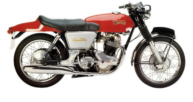
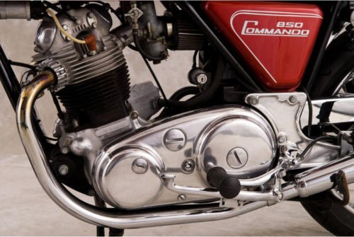
34. SO CALLED ‘SUPERBLEND’ MAIN BEARINGS. (All measurements were taken
with a micrometer / my even then olde pair of eyes and are approximate).
When the Commando main bearing problem started to occur the D.S roller bearing was
a Ransome and Marles MRJA30 bearing but with a brass cage and a designation
8MRJA30.The roller elements were the std. shape for that time having 11 rollers
11.12mm in diameter, 11.12mm in length with a parallel working surface of 10mm with a
very small std. radius to the corners at each end. It had load values of Static 36,200
Newtons and Dynamic 41,900 Newtons. (The T.S. bearing was a brass-caged 6306 ball
race bearing.) Personally I used to use the higher load capacity M306 ball race bearing
but we did have a bearing factory in town in those days.
In use on the more highly tuned Commando, due to crank flex the tiny area at the edges
of the 10mm rollers’ parallel portion would be the only points of contact with the inner
and outer raceways which damaged the hard surfaces of the raceways and rollers
leading to quick failure.(4000 miles?).
ONE of the MANY solutions required to solve the Commando main bearing failure
problem was a change in the bearing rolling element design to what became known to
Norton owners as ‘super blend’ where the rollers had a narrower central parallel portion
with each end slightly radiused for a mm. plus of length which allowed the crank to flex
more within the raceways without the edges digging in and increased the contact area
within the raceways as the crank flexed, compared to the older bearing that is.
I believe there are a couple of technical terms for the shape one of which is logarithmic
profiling. The number of rollers increased to 13, the width and diameter of the rollers
reduced to 9.53mm with the parallel part of the roller reduced to 6mm with the special
slight radius at each end reducing to 9.46mm. This brass caged bearing manufactured
by what had by then become RHP (Ransome Hoffman Pollard) and produced at the old
Ransome and Marles factory at Newark had an old R&M designation of 6MRJA30 with
the ‘6’engraved into the side of the outer raceway and the rest of the designation
stamped on. The inner raceway being stamped MRJA30.
The load values for the new ‘super blend’ bearing were lower than that of the original
8MRJA30 bearing it replaced and were Static 31,000N and Dynamic 35,800N. The
Nicholson ‘bible’ Modern Motor Cycle Mechanics gives 6MRJA30 as the bearing to be
used and tells owners NOT to use the one marked 8MRJA30.
I find it interesting that the new bearing which partly helped cure the main bearing failure
problem did not require similar or higher load values than the bearing it replaced. A
gentleman at the Newark factory kindly calculated the load values for the two bearings
for me after digging out the drawings from the cellars. I suspect the drawings along with
those for an engine bearing used on a Bristol Bulldog fighter or something similar which
the gent had just dug out for another query when I phoned have long since gone.
93
In that Motor Cycle Sport article mentioned earlier (Jan 77 pages 27/28) the writer
states that another manufacturers bearings had been tried but that yet another
manufacturers bearings ended up being used as they proved better and at one time in a
Birmingham warehouse full to the brim with cheap new and part finished BSA Triumph
and Norton parts were a small pile of SKF bearings we were told had come from Norton
and I SUSPECT these were the original ones tried. There were two types and we
bought a few of each. These ‘barrel’ shaped roller bearings were made by SKF in two
forms, a std. bearing and a high load capacity version both having a steel cage. One
came in boxes marked SKF. NJ306. 1972, which had 11 rollers of 10mm diameter with
a 7mm wide parallel section with a radius at each end tapering to 9.97mm. Load values
were static 20,000N and Dynamic 36,900N. The other bearing came in boxes marked
SKF. NJ306E.1972. (the ‘E’ designates extra load capacity) and employed 12 rollers of
12mm width and 11 mm diameter with a 9mm wide parallel portion reducing to
10.97mm at the end of the slight radius. Load values were Static 53,000N and Dynamic
57,000N. All load values being calculated for me by a Gentleman at SKF and I suspect
the NJ306 static one is incorrect but I am not going to try to have SKF check it for me.
After Norton etc. had ‘gone’ in one Birmingham emporium were probably several
hundred RHP boxes each containing the old Atlas ball or roller mains, 8 bearings to a
box and if memory is correct £8 for a box of ball bearings and £12 for a box of roller
bearings. One dealer I believe then advertised the roller bearings for sale at £12 each
referring to the brass cage as bronze. Not a bad profit margin. Out of curiosity I spent a
couple of hours moving boxes and found two marked 6MRJA30 which, after checking
the contents were the 6MRJA30 version I bought for £12 per box but have given most
away to friends over the years thus ensuring another loss making exercise! At around
this time most bearing manufacturers were changing or had changed the shape of their
roller bearing rolling elements to include some slight ‘barrel shaping’ to the ends of the
rollers, whatever the technical term for it is and this included FAG, RHP Steyr etc…
The FAG ‘Super blend’ NJ306E bearing is just a brass caged high load capacity version
of their std. NJ306 bearing but the rollers have slightly less radius than the special RHP
6MRJA30 bearings and I found it interesting to note that every old 6MRJA30 bearing I
have seen that have been taken from old motors has wear marking on the rollers but
not quite to the very edge whereas all the FAG ones (mainly fitted to 820 motors) show
wear to the very edge of the rollers, probably because they don’t have as much
reduction in diameter toward the outer edges but I suspect that the wear markings will
have a bit to do with how the motor was used during its (short?) life.
So why did Norton change to using FAG bearings? When I asked a couple of NVT
gentlemen the answer given was that they were cheaper and FAG were just down the
road.
The FAG NJ306E bearing I looked at had 12 rollers of 12mm width and 11mm diameter
with a 8mm parallel section reducing to 10.97mm at the end of the radius. Load values
being given in the book as Static 48,000N and Dynamic 51,000N. For a RHP
NUP306ETN bearing as used in later Triumph twins the one I looked at had 12 rollers of
12mm width and 11mm diameter with an approximately 9mm parallel section reducing
to 10.96mm at the edges. I lost interest in measuring other manufacturers bearing
products just to satisfy my curiosity.
94
So really the only special barrel shaped roller ‘Super blend’ main bearings made for
Norton motor cycles were the original R&M 6MRJA30 which have not been made or
been available for decades.
WARNING. Many years ago one dealer bought a pile of very cheap FAG NJ306E
brass caged bearings thinking they were SUPERBLEND… I opened one up and
could visually see NO sign that the rollers were radiused as one can if you catch
the light correctly. ‘Popping’ a roller out, the micrometer showed it not to be
‘super blended’. Phoning FAG they suggested they must have been old stock
held by a stockist from the days before the roller shape changed.
The dealer still sold them for Commando use and I wonder how long they lasted
in service. Bet no one ever just ran a light over the rollers to check they were the
correct bearings but why would they have done so?
There could still be a few appearing at auto jumbles so BEWARE - but that applies for
most things produced for our old Brit Bikes these days and I won’t mention the made a
few years ago now………….
NOT genuine Norton spares gears with the stress raisers at the base of the
engaging dogs so they break off in service doing the gearbox very little good!
or the incorrectly made not genuine Norton spares Commando clutch centres
with the oversize bearing seats so that IF you actually manage to fit them into the
bearing the bearing becomes so tight they are a bugger to rotate and ones clutch
does not free off correctly….
As for the gear sets made MANY years ago (shortly after NVT went to the wall)
where some idiots mixed up the different pitch diameter Dommy and Commando
gears so that when fitted the two gears in mesh were running far too tightly
together and it was difficult to get the inner cover to fit onto the main and lay
shafts… Once together things sort of worked, but I bet a few miles down the road
the boxes locked up… The gears were black in colour and if memory is correct a
complete set of gears and shafts cost £20 for cash! A dealer friend had bought a
complete set and asked me to build up a box to check them out before he bought
more of them. A faint memory tells me the engaging dogs were not undercut
either. One dealer started advertising and selling them as complete sets but
eventually ended up advertising and selling only part sets. Wonder how many
owners had been down the road on their rears before the dealer realised
something was wrong with them?
As for the NON-Surflex Commando so-called friction plates I bought in 2010 from
a UK company to check out - not only did they not have an aluminium alloy core
but they were NOT even a rigid moulded friction material… Add to that the spline
came no-where near fitting correctly splined clutch centres (or even undersize
incorrectly made ones!) and it would give a really skilled person a hard job taking
many hours to file them to the correct involute tooth form so they correctly fitted
correctly made centres. Having my friendly University do some shear strength
tests on one of the plates showed it to have a shear strength of less than 3000 lb.
/ sq. inch which is less than 1/3 rd the shear strength of the early Commando solid
fibre asbestos based DON 112 friction plate (9,000 lb / sq inch)! Don’t be
surprised if after buying and filing the teeth to fit the centres the teeth drop off
within a few miles of use… assuming you can actually get the clutch to free off
with these flexible friction plates fitted!


95
A friend who builds very reliable ‘less’ vibrating 650 SS motors for himself and friends
fits main bearings with internal clearances such that with everything cold the cranks can
just be turned by hand. His theory is that by the time the cases have expanded a tad
due to heat, as have the bearing outer raceway, there is more than enough room for the
oil required but not so much that the crank bounces up and down within the outer
raceway causing vibes when things reach full working temperature. As I have found C4
‘oooo’ fit roller bearings in old crankcases with a couple of thou internal clearance when
cold he could be correct - although having discussed with a bearing designer why
internal clearances are greater in roller bearings than ball bearings of the same physical
size and ‘fit’ I feel he may be over doing it a tad. Mind you his own 650SS motor has
done over 80,000 miles like that and is still going strong. However he also assembles
the cranks so both big ends go up and down together unlike I suspect many std. cranks.
He first assembles them with undersize studs / bolts moving each half till both big ends
are in line and then after tightening them and rechecking everything removes one bolt at
a time and reams that hole to accept a next size up high tensile fitting bolt or stud (such
as the 3/8 late crank ones or 8mm ones). Then he does a second one probably doing all
4 accessible ones. He also had his cranks ground by a company at Southampton who
insisted on being given the rods and new shells he was using because shells from one
manufacturer used to give different clearance on the crank to the shells of another
manufacturer. (I didn’t believe it till a gentleman in Birmingham sent me the shell
dimensions taken from Vandervell and A.P. drawings…which explained why a rod
assembled with one manufacturers shells was tighter on the crank than when using the
other manufacturers shells).
Wonder what the shells made these days are like on sizes and fits on correct size big
ends?
According to Mr Hopwood the 500 Dommy crank was designed such that at least one of
the two outer bolts above the big end was a fitting bolt in the flywheel and crank halves.
Having measured a few non genuine replacement crank bolt and stud kits over the
decades and finding many with every stud and bolt undersize it would not surprise me if
many motors have incorrectly aligned cranks. Of course when I mentioned this to a
certain Norton Gentleman friend he replied to me, for the second time in his life ‘Oh I
thought you knew all about that problem’ adding ‘I have been correctly aligning and
fitting proper fitting bolts into Norton cranks for customers for decades’. When he later
checked my ex-police MK2A crank the big ends were 0.010 inch out to each other,
probably with the help of the police ‘mechanics’ who had reassembled it last (using a
serious amount of Loctite). Wonder if correcting the error makes any difference to the
motors vibes? I very much doubt it. Once completely rebuilt by a friend my Commando
was sold and I didn’t even get to sit on it which was probably just as well.
96
35. BARRELS.
I once put a std. bore 500 Dommy barrel with no noticeable wear and new pistons on a
bottom end leaving the rings off of the pistons.
Holding the top of one piston it would move a few thou sideways and front to back but
the other piston would not. Checking the rods and even changing them over did not
alter things. Eventually, after much head scratching etc., I eventually went and -
checking the obvious - measured the gap between the bores each end of the barrel and
found a 0.005 inch difference!
I then asked the Norton Gentleman friend if this was common and was told bores not
parallel to each other and / or not at right angles to the base flange were not uncommon
just like the top face not being parallel with the base flange which is why you never bore
a Norton barrel bolted down on their top face!
Mind you it was understandable had you ever seen the boring jig I once saw in use in
Birmingham after NVT had closed! However new 820 and 750 barrels that required
boring CORRECTLY to +10 or +20 were VERY cheap as were genuine plus 10 and 20
pistons at the time.
The advice I have been given is, even if it costs more, to INSIST the barrel is
clamped down on identical sized packing pieces on its base flange for boring and
get the top face clocked and skimmed if required.
36. SPEEDING UP THE OIL PUMPS… A RAMIFICATION?
Spent a lot of time in my youth with a smoking Dommy. Nothing like an Ariel Arrow or
Leader you understand but enough to notice and have people telling me about my
smoking motor….. I had fitted the oil pump double speed worm gear recommended as a
tuning must have. So I changed the rings with no effect. I was then advised to fit Twiflex
oil control rings which I fitted with once again no improvement. Then my friendly ex
AMC race mechanic suggested I should look inside the rocker box with the motor
running……I did and apart from the inlet rockers covering me and the rear of the bike in
oil I watched at not much above tick over as the oil level built up to not only cover the
inlet guides but in practice it must have been running over the hump between the inlet
and exhaust sides and down past the followers to fill up the, at the time, NON existent
cam shaft oil bath! I bored out the inlet oil return holes in the head barrel and crank
cases with no effect……I ended up adding an external oil return from the side of the
head at a level just below the top of the inlet valve guides back to the timing chest…that
cured the problem. Any guesses why Norton shoved oil seals on the inlet valve guides?
Yet another bodge? Not long ago I was told that some people put a drain in the bottom
of the inlet valve area between the inlet ports back into the rear of the crank cases.
97
37. EXHAUST SYSTEMS. It took me decades to learn this lesson……….
My Dommy came straight off the track. It had no lights, a bulb horn. no kickstart or
alternator and in the motor flat top pistons, std size valves, std 650SS cam and flat
followers, twin monoblocks rubber mounted on extensions and they only just failed to
clout the 1 gallon 1954 Manx central oil rank. The exhaust system had swept backs with
GENUINE Gold Star silencers if that’s what one could call them…. the ones where a
broom handle would completely disappear in one end and appear at the other end……
IT FLEW - 7000 rpm in top and it still gave a kick in the rear. It also woke up anyone
within a mile or so which drew attention from those you don’t want to notice you……I
fitted pattern Gold Star silencers which made the lump less noticeable BUT instantly lost
well over 1000rpm in top…at 6000 it died….. I tried new pipes with the balance
pipe….NO effect…. I tried different super-duper ‘silencers’ all with no improvement so
basically I gave up till one day I was at a Brands Hatch practice day watching a friend
rushing around on the new Atlas he had bought to play with. It had only the standard
small bore Atlas primary pipes fitted. I asked if he would take my Dommy out if I fitted
his Atlas pipes on it. We fitted the pipes and I bumped it down the paddock hill….It was
as if someone had replaced the engine with a real one. He ended up lapping a second
or two quicker on my old Dommy with its front brake that needed skimming… That was
the day I learnt one of the things to getting Norton twins to go well was a something like
correct primary length exhaust system.
Personally for exhaust design these days I use the formulae given in the book ‘4 Stroke
Performance Tuning’ and having had a certain tuning Company use their computer
design system to see what they came up with gave exactly the same result..
38. PETROL TAPS. A really silly one.
In my youth when I knew even less than I do now but thought I knew it all I once had
problems for a long time with a bike that would slow when holding the throttle well open
for a long period of time…..even with a gale up my rear along say ‘The Mountain Mile.’ I
could NOT understand till one day I wondered….. 120mph….30 miles per gallon? 4
gallons per hour = 32 pints per hour = one pint every 1 min 52 seconds……Placed the
tank on two chairs put a pint pot beneath and turned the tap on……one pint in 2
minutes 20 seconds………..Q. E. D. Cause? The new petrol tap I had fitted had too
small a bore and I was suffering increasing petrol starvation the longer the throttle was
wide open.
One of those nice big bore brass chromed ‘Enots’ gas type taps instantly solved that
problem. A friend had a similar problem not long ago…we EVENTUALLY found the crap
they put in petrol had resulted in the neoprene seal expanding and partly blocking off
the fuel flow through the tap.. Av gas once caused the ‘rubber’ tube we had used to
flexibly mount the carbs on our Atlases to swell and partly block off one inlet tract
causing somewhat erratic running….so stupid a reason for the engine not working
correctly we never thought to check it and only found it when someone took a look down
the inlet tract with the slide fully retracted…..
THE END.
98
BELT PRIMARY DRIVE SYSTEMS
39. Introduction.
A subject probably totally boring for most people but which might contain information of
which those interested in the subject may not be aware and those considering buying a
belt system really should be! Some of this I put together a great many years ago
intending to submit it for publishing in the Norton Owners Club magazine Roadholder
but I and several friends left the club before doing so and as it has sat unwanted /
undeleted on my computer ever since now would seem a good time to get it finished
and out of the way. I have added further sections and updated some others.
I know of NO belt used for motorcycle primary drive that was originally designed
to be employed with oil and that includes the Synchroflex, Gates and Megadyne
polyurethane AT10 belts all having been designed to be employed DRY. Any form of
lubricant on ANY of the toothed belts we employ simply increases the risk of the belt
ratcheting (jumping pulley teeth) resulting in belt failure occurring.
99
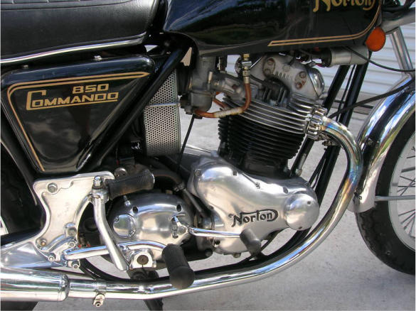
40. A QUICK(ISH) HISTORY OF THE BELTS WE USE FOR PRIMARY DRIVE.
Possibly not totally accurate but until a retired belt industry gentleman completes the
writing of such a history and publishes it on Wikipedia…….
As far as I am aware (and according to Super Cycle Magazine) the first internal toothed
belt was invented / developed in the 1940s for The Singer Co. by a Mr Case working for
the Gilmer Co. in the USA. It employed a trapezoidal tooth form with widely spaced 20
degree straight sided teeth. The Gilmer Co and patents were taken over by ‘U.S.
Rubber’ who became ‘Uniroyal’. The Uniroyal ‘Gilmer’ belt underwent a lot of
development over the years with for example the straight sides of the trapezoidal teeth
changing to an involute gear tooth-form so that instead of the low friction nylon tooth
facing of the belt teeth sliding into mesh with the pulley teeth resulting in wear and
efficiency loss they ‘rolled’ into mesh increasing both efficiency and belt / pulley life.
Naturally they patented the new tooth form and other manufacturers had to licence it or
continue using the straight sided tooth form. Also the steel wire tensile member was
changed to glass fibre as it gave improved belt flexing characteristics increasing belt life
and improved adhesion with the neoprene along with probably increasing efficiency.
However the demand for a fibre glass material that was compatible with polyurethane
was so small no one at the time produced it and polyurethane belt manufacturers had to
continue employing steel wire as the tensile member.
The Uniroyal PowerGrip trapezoidal tooth form STOCK belts of the 1960s had STOCK
pitches ranging from 1/5 inch to 1¼ inch. i.e. from very small carrying fractions of a H.P.
to BIG carrying lots of H.P. in industry. (I will later explain the Uniroyal / Gates meaning
of ‘STOCK’ as ‘some’ people are I believe unaware as to its meaning). Uniroyal also
made these neoprene trapezoidal tooth form belts for other ‘manufacturers putting the
other manufacturers’ names on them along with licensing other manufacturers to
produce them. The major problem with the trapezoidal tooth form belts was / is that
torque concentrates the stresses at the root of the belt teeth and the belt teeth strip long
before the belt tensile member becomes anything like fully loaded. I understand the
listed power ratings of the Uniroyal PowerGrip trapezoidal tooth form neoprene belts
were only using approximately 1/17 (one seventeenth) of the actual max tensile strength
of their fibre glass tensile member. i.e.: the weak link was / is the tooth form and not the
fibre glass tensile member used and it is little use using a belt for our primary drives that
could be used as a strop with which to hang a lump weighing 10 tons plus if when used
to transmit / carry the torque output of your motor the teeth strip. I believe some modern
tooth form belt power ratings employ something like ¼ of the tensile members max
strength. To overcome the low torque carrying capacity of the trapezoidal tooth form
people simply employed wide belts (or in industry several belts running side by side)
and is one explanation as to why American motor cycle early after-market trapezoidal
tooth form primary belt systems on Harleys etc. were so wide.
One day in 1966 in a pub outside Edinburgh a Mr Jeff Cox (Development Manager?)
sketched on a bit of paper for the assembled fellow Uniroyal staff to see a new curved
tooth form stating this was going to be the tooth form of the next generation of belts. At
Uniroyal in the USA I understand a Mr Henry Miller did a lot of serious mathematics that
ended up in the new curvilinear tooth form and PowerGrip HTD belts becoming reality in
the early 70s. I was told that Mr Millers’ name was on the original patent. I am going to
refer to the then new Uniroyal PowerGrip HTD tooth form belts simply as HTD (High
Torque Drive) from here on.
100
It was ‘suggested’ to me that with the new HTD belt the people tasked with laying out
the HTD power tables were told to be very conservative as the Company did NOT want
any belt failures to occur over the following years that could in any way be blamed on
their World leading and hopefully large profit making new belt that had cost a serious
amount of time and money to develop and put into production. Even so with their new 3,
5, 8, 14 and 20mm pitch HTD belts the new tooth form belts, when compared to earlier
trapezoidal tooth form belts of the same size increased in the design manuals the
torque a belt could transmit by up to 50% enabling designers to design smaller belt
systems or carry more ‘grunt’ for the same size belt.
Of course for other manufacturers to - much later - introduce new belts in an
effort to compete with Uniroyal it would have been pointless if their new belts did
not show equal or greater power ratings…wouldn’t it?
And, as a Gentleman who will have seen and studied test results for all competitors
competitive belt products once commented to me, as we discussed the subject of some
manufacturers power tables: “Any manufacturer can put whatever they like in their
power tables, it does not mean the tables have any basis in fact”.
Thus Uniroyal had a new belt that became the World leader which, as they had been
clever enough to patent the tooth form, gave them many years lead in the World-wide
industrial power transmission belt system business. Thus other manufacturers (those
who could afford to do so) had to go and spend lots of their time and money developing
their own new tooth forms with which to eventually try to compete with Uniroyal for new
and replacement belt business without infringing the Uniroyal patents.
To ensure automobile manufacturers ended up with the two separate suppliers of the
new HTD belt they required before using it Uniroyal licensed Continental to manufacture
HTD belts. So it came to pass that Uniroyal HTD tooth form belt systems became used
by industry and the auto industry around the World in vast numbers long before any
other manufacturer managed to even start to get a look in which I suspect made the
Uniroyal power transmission / auto divisions very profitable and the stock holders very
happy.
However, as someone reminded me the other day, these belt manufacturing ‘rubber’
companies also made car tyres and introduced radial tyres which very seriously
outlasted their old cross ply tyres many times over so new tyre sales eventually reduced
dramatically causing the companies serious financial problems. Not that ONE European
manufacturer’s radial tyres gave much grip in the wet as I remember it.
In the mid 70’s Goodyear tried and failed to license the new HTD tooth form so
Goodyear and other manufacturers probable bought a few HTD systems and tested
them using modern test equipment to see where things could be improved, IF they
could.
101
In the late 70s both Goodyear and Pirelli introduced new tooth forms which did not
infringe the HTD patents the Goodyear one being known as SuperTorque P.D. (power
drive) and the Pirelli one RPP-HPR both of which employed pulley and belt tooth forms
different to HTD and thus in theory one could / should not use these belts as after-
market replacements for running on the HTD pulley systems that had flooded industry
over the preceding years. I believe the Pirelli power transmission division was later sold
off initially to Dayco and then on to Megadyne (Carlisle Group) who now market Gold
and Silver versions of this belt which can, so they state, be employed with HTD pulleys
and I have used the 8mmm pitch Silver version on HTD pulleys with success (to date)
where the belt length required is not a stock Gates length but whether they will give the
same belt life as one would obtain with a Gates manufactured HTD tooth form belt
employed on HTD pulleys I have no idea. However I was told that testing had shown the
RPP-HPR belt to run better on HTD tooth form pulleys than it did on RPP-HPR tooth
form pulleys. (I was also told that Dayco had retained the Pirelli automotive division).
Other manufacturers had to go do their own development to try to compete with the
Uniroyal HTD belt and the Synchroflex manufacturer came up with their AT belt range of
which the AT10 10mm pitch belts are one and it was basically an update of their earlier
T10 belt employing longer teeth on the belt and shorter teeth on the pulley while
retaining a trapezoidal tooth form and steel wire tensile member, the root of the teeth on
the belt having a greater radius where they join the main carcass all of which I assume
was to reduce the tooth shear problem and increase the power ratings so as to try to
compete. A couple of years ago it was further ‘improved’ with the introduction of a
‘Generation 3’ version but it still retains a trapezoidal tooth form and steel wire tensile
member even if a pretty red in colour.
(Personally IF having to choose a polyurethane belt for power transmission on colour
alone I prefer the blue coloured Bando belt with its non-trapezoidal tooth form).
I was told that it was after the Uniroyal HTD patents had expired that Gates introduced
their polyurethane 8 and 14mm pitch Polychain belts originally employing the HTD tooth
form and a Kevlar tensile member. Note that unlike the Synchroflex, Gates and
Megadyne AT10 polyurethane belts the Gates Polychain polyurethane belts employ /
employed a low friction tooth facing just like the Uniroyal (now Gates) and Megadyne
etc. neoprene belts (and the latest Continental polyurethane belts) probably because
Gates Polychain belts are used carrying up to ten times more load than equivalent AT10
belts and I was told testing has shown them to significantly outlast AT10 belts whilst
doing so. I believe only the 14mm pitch Polychain belt was originally made available in
Europe. It is a slightly different ‘GT’ tooth form on stock 8 and 14mm pitch Polychain
belts these days with the latest version employing a ‘carbon’ fibre tensile member and
they kick every other industrial toothed belt into the weeds torque carrying capacity
wise. I believe that the 11 mm pitch Polychain belt fitted to the rear end of Harleys
employs the original HTD tooth form as it is more suitable for motor cycle use where
belt tension and load changes etc. occur all the time. (Many years ago ‘Gates’ bought
the ‘Uniroyal’ power transmission business and all the belts became referred to as
Gates belts. I believe they were then bought by a British investment group (Tonkin) but
that they have since sold it on to a Canadian pension fund).
102
These days there are lots of different belt manufacturers with each one probably telling
the World that their belt and its tooth form and / or construction is the greatest thing
since sliced bread and I have no doubt the bullshit totally baffles many brains. Did not
someone at Buell once believe and change from using a Gates Polychain belt on the
rear end of their bikes for those of another manufacturer? I believe Buell changed back
to employing the Gates belt before being closed down. One friend on his Buell left his
NON Gates rear belt laying in the road after approx 15,000 miles which I understand did
not endear that belt company to him. Certainly the friends latest new Buell has a Gates
belt fitted.
A few years ago Gates tried to introduce a standard test for 8 mm pitch belts but
apparently the idea went down with the other manufacturers like a proverbial lead
balloon. (Wonder why if their belts were superior?).
What they proposed was to run each 8mm pitch belt, 20mm wide (which was the
industry smallest std. width) on its own 28 tooth pulley at 2560 rpm and determine from
the testing the nominal torque at which each belt would achieve a life of 10 to the power
7 (ten million) belt cycles which is apparently a test similar in concept to that used for
flexible shaft couplings (DIN740). As the Gates test results give an indication of the
advances made in belt technology over the years by some belt manufacturers I will list
them.
Basically they show: First generation 8mm pitch curvilinear (HTD) tooth form belts up to
30 Newton meters. Second generation over 30 Newton meters and third generation
over 60 Newton meters. Remember that these are for 20mm wide belts.
Whether they were published on the web I know not: but the only test results I have
seen that include the AT10 belt were headed ‘8 / 10mm Pitch Benchmark AT10 / HTD /
Polychain GT2’ for 20mm wide AT10 and HTD and 12mm wide Polychain GT2 belts
with Tension (horizontal axis) against Test Cycles (vertical axis) and the AT10 results
only just about make it onto the results graph sheet with the HTD belt coming out
significantly better in both tension and belt cycles and the narrower Polychain belt
coming out significantly better than the HTD belt in both tension and belt cycles.
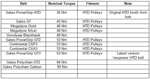
103
42. UNIROYAL / GATES STOCK BELTS.
A motor cycle belt system maker once told the World how the 10mm pitch AT10 belts
he employed were available in a greater number of different lengths than were the 8mm
‘neoprene’ belts enabling him to make systems for more different motorcycles and it is a
fact that when comparing the lists in my olde Uniroyal (now Gates) 8mm pitch HTD and
Synchroflex AT10 design manuals then the AT10 belt is shown to be available in a
greater number of different lengths than the 8mm pitch HTD belt.
Now it may even be fact that the AT10 belt is available from the manufacturer in more
different lengths but there is one important difference between the two manufacturer’s
lists of which the system maker was, I suspect, unaware or did not want people to
know…
The difference is that while my old Synchroflex AT10 list even shows belt lengths
marked as being ‘in preparation’ at the time the list was drawn up the Uniroyal HTD list
is headed STOCK BELTS and it shows ONLY the different lengths of the 8mm pitch
HTD belts that are held IN STOCK around the World so as to be quickly easily and
reasonably economically available to their customers and it is NOT a list of all the
different lengths they do or can make of this belt because in their numerous
manufacturing plants around the World they hold NON stock length moulds with which
they can and do manufacture NON stock length belts. However I believe the Gates
mould list is regarded as Company Confidential. Even so I know of a couple of non
stock lengths and the other day for example while making enquiries for a friend I was
informed of a another non stock length 8mm HTD belt mould was held by two
manufacturing plants in the Far East.
However if you employ a belt system that employs an old Uniroyal or Gates 8mm pitch
HTD stock length belt then a replacement belt should be available to you within one
working day in every major country around the World whereas non-stock lengths and
other manufacturers belts may not (will not?) be available in this manner simply
because they do not have the same World-wide distribution network.
For example a great many years ago after reading that system makers blurb regarding
belt lengths I decided I would check up on the availability of Synchroflex AT10 belts in
the USA and phoned the listed East Coast USA Synchroflex agents asking if a listed
880mm x 32mm Synchroflex AT10 belt was available and was informed it was but that
they would have to first obtain it from Europe which is NOT what you would want to hear
when your Synchroflex AT10 belt has just failed although it could be the case these
days that a Gates manufactured stock AT10 belt of the same length could be easily
available from any local bearing / belt distributor…
Apparently it was way back in time long before HTD belts appeared that Uniroyal
decided to make their V and trapezoidal tooth form PowerGrip belts available World-
wide but even in those days the number of different belts available was far larger than
could be economically and probably physically held in stock around the World so
someone must have been tasked with coming up with a list of pitches lengths widths
and a standard construction material specification for the PowerGrip belts that would
satisfy the requirements in the majority of cases of industrial equipment designers /
manufacturers and these became the STOCK belts.
104
Anyone can go design something using NON standard bearings or even NON standard
chain but where do you now obtain a non-standard bearing or chain for your bike when
they have not been manufactured for decades? Triumph for example on the T150 and
T160s employed a non-standard duplex primary chain but unless you are sitting on a
pile of new ones (making you potentially rich) they have not been available for many
years and to replace one now I understand you end up buying two new sprockets
employing two singlex chains which hopefully are standard chain! Then there were the
‘special’ roller and ball race main bearings with greater than standard radiuses on the
inner raceway allowing designers to include nice large stress reducing radiuses on their
crank shafts etc. but unless someone has expensively had a batch made or modified
some standard bearings where are you going to obtain a new replacement now?
105

43. BELTS AND OIL.
The use of any of the belts we use with any form of lubrication on them increases
the risk of the belt jumping pulley teeth (ratcheting) especially when a loose belt
is employed and / or high torque is applied.
Ratcheting will result in stripping teeth from the belt and / or belt breakage and testing
has shown that even when employed dry with the same belt tension applied trapezoidal
tooth form belts are far more prone to ratcheting than are HTD tooth form belts with their
deeper teeth.
A picture of an AT10 belt minus a few teeth appeared in Triple Echo magazine (No. 57
Dec 87 / Jan 88) and the owner stated in his letter that this was the second time it had
occurred and that he felt the belt did not appreciate him dropping the clutch at high revs.
He also stated the chain system had been refitted and the belt system, complete with
yet another replacement belt, was for sale. He also stated that the system maker
thought the first failure could only be due to a faulty belt. A friend once shared a garage
in ‘The Island’ for the Manx G.P. with a Gentleman racing a 3 employing an AT10 belt
primary. During practice the belt proved’ unreliable’ with the original chain system being
obtained and refitted. As to the cause of the belt problem I have no idea (nor do I care)
but if the belt was being employed with oil I would suggest that ‘ratcheting’ could be a
cause worth considering.
Knowing a Gentleman who for many years’ prepared BSA / Triumph 3 road and race
engines (and fell off his own on the odd occasion whilst racing), I heard more than once
from him where AT10 belts had failed putting bits of steel wire tensile member etc.
through engines with disastrous consequences for the owners pockets!
I even spoke to one of the not happy owners and he stated that the Midlands dealer
who had sold him the AT10 belt system for his classic race BSA3 refunded the cost of
the system - but I don’t suppose they also paid for the very expensive complete engine
rebuild the friend did for him!
However, not having seen the systems, I have no idea as to the cause of the failures.
Mind you whoever introduced on production bikes breathing into the chain case with the
oil going back into the engine was in my opinion, to be VERY polite, not clever…
especially the one who on the B50s neglected to also include the 3 small drain holes
back into the crankcase as late Triumph twins have to limit the oil level in the chain
case so it does not flood the clutch resulting in even greater slip problems than normal
AND I have a copy of the B50 D.S. crankcase machining drawing 71-1214 beside which
shows NO drain holes nor are there any on the CCM scrambles motor or B50 bottom
half sitting on my bench OR any B50 crank case I have ever seen.
The ONLY reason I was given for Triumph breathing into the chain case on their
road bikes was because of the number of bikes coming through the service
department with rusty damn nigh solid primary chains thanks to the
incompetence of the owners so it was thought a good idea to ensure the correct
oil level in the chain case… automatically… that is till the owners allowed the
engine to run out of oil!
Mind you that was only a tale I heard from a Gentleman in the Triumph service
department.
106
I heard that initially Mr Hele only removed the crank oil seal on the bikes being raced at
Daytona simply to overcome a crankcase breathing problem. Personally I like all
breather pipes being taken back to the oil tank with a BMW motor cycle crank case
breather reed valve fitted into the top although I am told that the very simple system
Triumph at one time employed works very well…as I understand testing conducted
many years ago by Mr Oswald of QPD in the USA has shown.
Some ratcheting test results.
As, to my knowledge, Gates etc. do not list 10mm pitch HTD belts and the polyurethane
AT range of belts do not include 8mm pitch belts but 5 mm pitch belts of both types are
made these were employed for the test. The three same width 5mm pitch belts used for
the testing were... Synchro-power AT5 trapezoidal tooth form. Synchroflex AT5
trapezoidal tooth form. Gates GT HTD tooth form. All using their respective 28t tooth
form pulleys.
With a belt tension of 50 Newtons applied to each belt, the Synchro-power belt
ratcheted when a torque of approximately 11 Newton meters was applied to the pulley,
the Synchroflex belt at approximately 13Nm and the Gates GT belt at approximately
34Nm. With a tension of 100 N. applied to the belts the Synchro-power belt ratcheted
when approximately 13Nm was applied to the pulley, the Synchroflex belt at
approximately 14Nm and the Gates GT belt at approximately 36.5Nm. The torque at
which ratcheting occurred only increased slightly when an increased belt tension of 200
N was applied. I asked if the different material tensile member would make much of a
difference and was told it would not.
Anyone want to have a stab at guessing why the belt on the rear of Harleys has an HTD
tooth form and not trapezoidal? No prize for getting the correct answer.
As the major benefit of employing a DRY primary belt system on say a Commando /
T140 / A65 / B50 etc. is, in my opinion, that it allows owners the chance to reasonably
economically obtain a correctly working dry clutch I personally cannot understand why
any owner would employ a primary belt system with oil.
Of course if some owners think their clutches were actually designed to work correctly
when run with oil simply because the bike manufacturer shoved the clutch within the oil
bath CHAIN case or told them so in the manual or simply because they have read or
heard incorrect information …………..One system maker once even recommended his
dry AT10 belt users employ grease on the belt…… (See later under misinformation).
107
Try to run a stock neoprene belt with oil and the belt will eventually try reverting
back to the oil it was made from in the first place and fail.
However for situations where oil cannot be avoided such as the one where a Gentleman
designed a system employing the cam drive belt also as the oil pump to supply oil for
small 4 stroke engine lubrication you would use a belt with a construction suitable for
the application and belt construction ‘suitable for use with commercial engine oil’ was
shown to be available decades ago even before HTD belts appeared but I suppose
‘some’ people have never bothered to look in design manuals to determine such facts
and noticed the many different constructions available… Of course I doubt such
constructions are available around the World over the counter. I understand oil
pressures of 60 Lb. /sq. inch plus were obtained and that someone bought the system
to use on their small 4 stroke engine hand held power tools. I found the patent by going
to Google, then ‘Patent search’ then shoving in ‘Woodhouse oil pump’ and down the list
that appeared it is the one ‘Engine lubrication system. US patent 60000373’.
However in running a belt with oil there are the problems of forcing the oil out from
between the belt and pulleys resulting in efficiency loss and probably increased belt
tension but I noticed earlier this year (2012) that Gates are now showing their latest all
singing / dancing Polychain Carbon belt to be available in a non-stock polyurethane
compound for use with hot oil in gear cases / transfer boxes etc. The pulley design
having been very seriously modified to incorporate ports in the base of each pulley tooth
to allow the oil that would otherwise become trapped between the belt and pulley to be
expelled before it results in ‘pumping’ losses and increased belt tension.
I suspect the pulley design will be very similar to that used for the Poly chain ‘carbon’
belt application for push bikes where ports in each pulley tooth allow the mud and water
to be expelled before causing a problem. Doubt they help expel tree trunks! My money
is on the patents having been written in such a way that no one else will come up with a
similar system for a seriously long time which could well be handy for Gates as I hear
automobile engine manufacturers want to run belts within their engines in the future
along with the engine oil. Yes I know some are considering reverting to chain…Wonder
if they have seen the test results I have showing the power losses, extra fuel
consumption etc. resulting from cam chain drive. Reading the Telegraph motoring
section the other day it would appear some German car company 1.4 litre car engines
are suffering chain problems and personally I was rather amazed to find they were
actually using chain. Don’t suppose they only previously only tried using belts with a
trapezoidal tooth form do you? I found the Gates push bike Polychain ‘Carbon’ bumph
on Google by inserting ‘Gates Push bike’.
108
44. BELT DRIVE ‘MISINFORMATION’ AND BULLS**T.
‘Misinformation’ regarding motor cycle belt systems and belts is not new and in fact in
the September 1977 Super Cycle Harley belt / chain dynamometer test article they
wrote something that all British bike owners thinking of buying a belt drive system would
be well advised to remember and continuously repeat to themselves whilst making their
belt system buying decision. They wrote:
“Unfortunately in the motor cycle belt world the makers have fairly muddied the
waters as far as the consumer is concerned. They have laid out claims they know
to be false, always exaggerated and they engage in an inordinate amount of
competition ridicule. All this is done to justify and promote the belt each maker
can easily obtain.”
(My note, for makers read SOME motor cycle belt system makers and dealers).
Unfortunately it was not long before some people imported the practice into the UK and
it was really their misinformation that gave my belt learning curve a kick up the
proverbial so as to learn a few facts thus these people have only themselves to
blame for these web pages.
In my opinion the greatest piece of belt misinformation that many have believed to be
fact is that the Synchroflex AT10 belt was designed to be employed with oil when in fact
IT WAS ORIGINALLY DESIGNED TO BE EMPLOYED DRY as the then Engineering
Director of the Synchroflex manufacturers UK agents stated to me in a letter dated 26-3-
87. (I still have the letter).
If you do not believe me go phone the Synchroflex belt manufacturer in Germany or
their UK agents and ask them if the SynchroflexAT10 belt was designed to be run in or
with oil (OR GREASE!) and learn the facts. They might even inform you of how
trapezoidal tooth form belts are more prone to ratcheting than are HTD tooth form belts
and how the problem increases if there is any form of lubrication on a belt… assuming
the person you are talking with actually knows about such things and as belts were
designed to be run dry why would they? I doubt the people at Renold have much if any
knowledge regarding the employing of their power transmission chain products DRY!
And why would they?
I once (2010) asked a Gentleman as to what type of belt he thought the most suitable
for our primary drive use and after a bit of a think he suggested an 8mm pitch neoprene
belt manufactured using an HTD tooth form mould but employing later more modern
construction materials as they give much greater power carrying capacity. Mind you the
ancient original construction 30mm wide HTD belts we employed on our olde Atlas’t
worked perfectly… once the incorrectly toothed British made pulleys had been correctly
toothed. Mind you we did replace the belt on a yearly basis.
The only real advantage to employing more modern belts being that narrower belts can
be employed which on our lumps places the pull on the gearbox main shaft closer to the
gear box bearing which is no bad thing plus it solves the problem of employing a belt
wider than a singlex chain but using narrower belts to carry the same power must
increase pulley wear… it is all a game of compromise and you never get something for
nothing. I note Gates are now stating that their new Polychain Carbon belt is as strong
as the same width chain and has a life 3 times greater……… Mind you they are
expensive and don’t run on HTD pulleys…………
109
45. A FEW EXAMPLES OF ‘MISINFORMATION’.
The following which appeared many years ago are from the N.O.C magazine
Roadholder and elsewhere such as the ‘bumph’ (information) sheets a U.K. system
maker sent prospective customers. (I ‘hear’ the system maker no longer supplies
‘bumph’ sheets). The system maker later referred to his misinformation contained in
Roadholder magazine as ‘no big deal errors’ after two letters were published in
Roadholder correcting some of his ‘misinformation’ for the benefit of Club members.
I will leave you to decide if his ‘errors’ were ‘no big deal’ and whether or not they may
have influenced the belt system buying decisions of some British motor cycle owners
around the World.
Since the following appeared I have tried very hard to avoid looking out for such
misinformation from system makers / dealers and friends are banned from telling me of
any they have found as learning of its existence does my blood pressure little good!
Mind you it didn’t stop one telling me not long ago that, according to Classic Bike Gold
Star clutches were wet clutches! Funny how they employed DRY USE ONLY friction
material from 1954-56 on the friction plates and on the chain wheel to the end of
production but I suppose if Cycle World could state Atlas clutches were wet clutches …
Roadholder. Issue 130. Nov/Dec 1986.
1. ‘Most of my 17 different belt drives use a belt of 20 to 32mm width. The Government
Power Spec Safe Working Load (SWL) for a 32mm wide belt is 86HP (breaking strain
being 3 times the safe working load)’.
2. Referring to the Goodyear Supertorque Pd and Uniroyal HTD 8mm pitch neoprene
belts… ‘However both the above have a Government Spec SWL of 50HP at 5,600 rpm
for 30mm width compared with 86 BHP at 10,000 rpm for my AT10 belt in 32mm width’.
3. ‘My BELTS can be run DRY but with reduced efficiency, hence I always tell my DRY
USERS to keep their belts well-greased’.
Roadholder. Issue 137. Jan/Feb 1988.
4. (The system maker has a change of mind about his belt, oil, grease and efficiency
after having a few FACTS presented to him in a couple of letters that appeared in
Roadholder Issues 132 and 133 correcting some of his what he later referred to as ‘no
big deal errors’). He wrote ‘The AT10 belt has 99% efficiency. If run submerged in oil
the efficiency reduces by less than 1%. This loss is so small it is difficult to measure’.
5. This particular system maker’s advertisements in motor cycle magazines claiming
the belts he used ‘are the strongest and highest revving belts in the World’.
Dealing with these: ‘no big deal errors’.
Number 5 first.
As the system maker was unable to prove his advertisement to be correct he was told
by the UK Advertising Standards Authority to remove or modify the advert. (Adjudication
date 26-9-2001).
The system maker then modified his advert to read ‘in my opinion it is the strongest and
highest revving…’ My opinion is somewhat different but there again I do have a copy of
some testing done by a major belt manufacturer comparing a couple of their 8mm pitch
neoprene belts and their AT10 polyurethane belt upon which to base my opinion, along
with picking the brains of people in the belt industry with decades of development, test
and operational belt experience for factual rather than fictional information.
110
Number 3 and 4.
Funny, but my old Synchroflex design manual only gives an efficiency value of ‘up to
98%’. Later on you will read that the UK Synchroflex agents wrote to me stating that no
testing with oil had been carried out. I am still waiting to find the owner with a pot of
Castrol LM grease attached to his or her bike so they can apply some to their AT10 belt
every so often!
Number 1.
There was and is no such thing as a ‘Government Power Spec Safe Working Load
S.W.L.’ no matter how ‘grand’ it sounds. The only quoted values were those given in the
British Standard, ISO and other national standards which were agreed by the various
manufacturers and represented the MINIMUM agreeable value ONLY. The ‘breaking
strain’ for Uniroyal glass fibre tensile member belts at the time was 17 times the rated
tension.
Number 2.
All the belts we employ really care about is the torque they are being required to carry /
transmit and the HTD, Goodyear and Megadyne neoprene belts mentioned will work
perfectly happily at much higher belt speeds and rpm than shown in their respective
‘industrial’ design manuals, just as the primary chains we employ can and do run at
much greater rpm and linear speeds than shown in their ‘industrial’ design manuals
although nothing like as ‘happily’ as belts can and do..
Many years ago being a tad fed up with the system makers ‘misinformation’ and with
people telling me all about this AT10 wonder belt with its fantastic power rating of 86HP
at 10,000rpm, designed to be / can be run in oil etc having believed to be fact the
‘misinformation’ they had read and / or heard; I wrote a letter to the Synchroflex belt
manufacturer in Germany asking a few questions to obtain some facts.
They referred the letter back to their UK agents for answering who kindly did so.
I sketched a ‘typical’ AT10 primary system employing a 32mm wide 880mm length
AT10 belt employed with a 28 tooth engine and 56 tooth clutch pulleys. I drew in an oil
level of SAE20 oil as it would be on a T140. Alongside I added engine rpm 0 to 7000. I
asked a few questions some of which were…
On the subject of oil and efficiency.
1. ‘Whether any testing has been carried out on this subject and, if so what power
losses caused by oil were obtained and what losses would occur with the system
shown.’
2. ‘If no testing has been carried out on this subject as to what sort of losses you think
may occur with the system shown’.
On the subject of power ratings.
3. ‘The claim has been made that your AT10 belt is rated at 86hp at 10,000rpm for a
belt width of 32mm without any mention of pulley size. Assuming a system as shown,
even without oil, would you please supply a calculated power rating at 10,000 rpm?’
4. ‘If a power rating of 86hp at 10,000rpm is incorrect have you ever supplied such a
power rating for a belt life based on 500 or 1000 hours’.
111
There were a couple of further questions which concerned the way in which the
Synchroflex AT10 power table was laid out.
In a letter dated 18-04-89 they replied. (Note the date of their reply and the date of the
system-makers statement No 4 published in Roadholder Issue 137. Jan-Feb 88).
I still have all the correspondence.
1 and 2. ‘No testing has actually been carried out on this subject. It would be very
difficult to establish the power losses in this system as the drive is not fully submerged.
We would however expect any pumping losses to be low due to the effects of
cavitation’.
3. ‘Calculated power rating at 10,000 rpm is 37.2 hp’.
4. ‘No power ratings have ever been supplied with these figures but it is well known in
all belts that you can transmit substantially higher than rated catalogue figures if you are
willing to accept a reduced belt life. What would be a reduced industrial belt life would
be a more than adequate life on a motor cycle’.
So where was that system maker obtaining his efficiency values from if no testing
with oil had been conducted (and please do NOT expect me to believe the system
maker had done such testing)?
The efficiency loss due to oil will depend on many variables such as the viscosity of the
oil, the depth of the oil with respect to the clutch pulley and belt , belt speed, belt
tension, width of belt, type of tooth form etc. and would be very time consuming and
expensive to conduct if done correctly.
At what belt speed would cavitation occur?
Could oil on a belt force the belt away from a pulley over tensioning a belt, especially
when first firing up the bike when the oil is cold?
Where was the system maker obtaining his power rating from? Thin air?
Are you one of those who actually believed such ‘misinformation’?
IF the Synchroflex AT10 belt was designed or intended to be employed with oil then
why had no testing with oil been conducted?
The answer being I suspect that as the Synchroflex AT10 belt was originally designed to
be run dry why conduct expensive and extensive testing with oil? I doubt Renold ever
tested their motor cycle chain products DRY although I suspect a few British bike
owners did and are still doing such testing! Mind you listening to the rear chains on lots
of big Japanese bikes these days they are also employing dry chains! (Because they
buy nice expensive ‘O’ or ‘X’ ring they must think it unimportant to lubricate the rollers
so the rollers get a tad of cushioning as they engage with the sprocket teeth….)
I know Uniroyal once conducted testing using their belts in sea water driving the props
of unmanned submersibles used for inspecting oil rigs etc. and that they recorded
significant power losses at low linear belt speeds due to pumping the water out from
between the belt and pulleys.
Did the system maker really think no one would bother to check up on his ‘facts’ with his
belt manufacturer? Although I bet VERY few people ever did; especially those editing
Roadholder and other club magazines such as Triple Echo (Issue 49) in which similar
‘misinformation’ also appeared, thus misleading their own Club members.
112
All the belts we employ are really concerned about is the torque they are being required
to carry / transmit and some power tables are calculated using constant torque so if you
increase the revs whilst maintaining the same torque you increase the H.P. Playing silly
buggers and applying that to the system makers 50 H.P. at 5,600 rpm for the 30mm
wide neoprene belts = 89.3 HP at 10,000 rpm which is greater than the system makers
claimed fictional 86 HP at 10,000 rpm for the 32mm wide belt he uses! This was pointed
out to me by a Norton Gentleman from the Midlands who at the same time as he did so
also sent me a big blown up picture of the system maker in question to attach to my
workshop door along with a set of foul tobacco smelling darts from a local pub so I could
amuse myself when the mood took me! I kid you not. The smell of the darts ensured I
NEVER took up smoking again after a heart op!! Not that I needed any encouragement
by then.
I get the impression the friend is none too keen on this system maker and his advice to
his customers asking whose belt systems they should buy is ‘interesting’ and has
greatly amused me whenever I have heard it given!
Other cans of worms ‘some’ people have ‘mentioned’ as they have I assume attempted
to show how unsuitable the Uniroyal / Gates and Goodyear neoprene belts are for our
primary drive use have been…
1. The Uniroyal PowerGrip HTD 8mm pitch belt power tables only show rpm up to 6000
(As do the Goodyear Supertorque PD. 8mm pitch belt power table) whereas the AT10
belts power tables show rpm to 10,000.
2. The Uniroyal 8mm pitch HTD power tables stop giving power ratings where belt
speed reaches approximately 6000 ft. per min but on the Synchroflex AT10 power
tables it occurs at approximately 7800 ft. per min.
3. The Uniroyal tables do not show power ratings for smaller pulleys at low rpm whereas
the Synchroflex AT10 tables do.
One system maker cleverly (I assume he thought so anyway) asked if one used a
system running in this unmarked area, does the power the Uniroyal belt is carrying
disappear into a black hole.
Regarding these, in as few pages as I can.
1. The predecessor to the AT10 belt was the T10 belt. Funny but the Synchroflex T10
power tables show rpm up to 15,000rpm. Does this make the T10 belt more suitable for
our use??? I think NOT but using the logic of some people……...
Taking my old 8mm pitch Uniroyal HTD power tables. They were laid out for
INDUSTRIAL use and NOT motor cycle use. My old ‘Renold chain drive selection chart
for Reynold stock series chain drives up to 140 H.P. (which includes our singlex duplex
and triplex primary chains) is also INDUSTRIAL and only shows rpm up to 3600rpm
which funnily enough is the no load synchronous rpm of a 2 pole A.C. induction motor
on a 60Hz supply, 4, 6 and 8 pole versions revving slower and slower still on a 50Hz
supply..
113
You don’t think motorcycle use of chain amounted to even 2% of total chain sales do
you? I would be surprised if it were even 1% when BSA Norton and Triumph were still
producing a few motor cycles and people actually rode them around wearing out and
replacing their chains fairly regularly. Yes I know SOME people do still ride their old Brit
bikes regularly and not just to and from the pub Sunday lunch times or for Club night
meets but such owners are few these days having bought more reliable start on the
button, stop with real brakes etc. etc. modern motor cycles for daily use.
IF you want higher rpm industrial power ratings for these belts you simply request them
and you get a reply such as one I received in 2001 for several different widths of the
then latest (GT) version of the Gates 8mm pitch Polychain belt which on a 34 tooth
pulley at 8000rpm were… 20mm width 38.1Kwatt / 51H.P…. 30mm width 54.3Kwatt /
72.7 H.P…. 36mm width 65.2Kwatt / 87.4H.P. Assuming constant torque you can work
out for yourselves the power ratings at 10,000 rpm if you really want to do so but I
suspect belt mass / centrifugal force will be somewhat affecting things by then and the
power ratings will also be reducing to allow for it, unless you increase belt tension so the
belt is still sitting in the pulleys correctly? Don’t know nor care as even my proposed
short stroke 90 degree crank 500 Dommy won’t rev to 10,000rpm. Not if the motor is to
stay as one lump, that is.
The Uniroyal (Gates) and Goodyear power tables tables are, just like the Renold chain
selection chart, laid out for industrial application use where minimum belt life is of the
order of 20,000 hours (Renold chain = a minimum life of 15,000 hours) and industry did
not and even now I very much doubt use many prime-movers / drivers revving above
even 5000rpm with probably 95% plus of prime movers being electric AC induction
motors. A little clue to this fact can be ascertained by actually looking at any 1960s and
later Uniroyal PowerGrip and HTD etc power tables noting the ‘funny’ rpms listed such
as 730, 870, 970, 1170, 1460, 1760, 2920, 3500 which are the approximately FULL load
rpms of 8, 6, 4 and 2 pole induction motors employed on 50 and 60 Hertz supplies.
Well they were (if my ancient memory is working correctly) when I was involved
building, testing and on the odd occasion helping install the often big lumps in my
younger days WHEN the UK still had some industry and produced such things… My
Goodyear Super Torque Pd. power table (probably because it was intended for the US
market) shows the ‘funny’ 60 Hertz rpms only.
Whilst the Uniroyal and Goodyear power tables only show rpm to 6000 the Goodyear
power table gives a power rating at 6000 rpm for an 84 tooth pulley which is a belt
speed of over 13,000 ft. per min whilst the system makers AT10 power tables stop
giving power ratings where belt speed reaches around 7,800 ft. per min. Some people
might even try to make something from that little fact!! Uniroyal / Gates has had and for
all I know still has 8mm pitch HTD belts working perfectly well for some applications at
speeds of up to 20,000 ft. per min. Mind you, our olde Brit bike engines will very
probably have gone BANG long before a belt speed of even 7,000 ft. per min is
reached!
114
The reason some belt manufacturers show no power ratings where belt speed
exceeds 6,000 ft per min. is SIMPLY one of safety……
When these tables were laid out decades ago many (if not most) industrial pulleys were
manufactured from cast iron and cast iron pulleys / discs etc. have an interesting but
seriously dangerous habit of exploding rather like a grenade when peripheral speed
exceeds around 6000/6500 ft. per min so Uniroyal gave no power ratings in this area.
If you wanted data in the unmarked area you simply requested it and as it was supplied
I suspect you would be warned of the danger and advice given… advice such as to
employ steel or aluminium alloy pulleys OR to change the design to reduce the
peripheral speed of the pulley. The 8mm pitch Goodyear Super Torque Pd tables may
show a belt speed of over 13.000 ft. per min BUT where belt speed exceeds 6500 ft per
min the area is shaded and a note states that special pulleys are required… The
SynchroflexAT10 table does not show this area but I suspect their pulleys are
manufactured from aluminium alloy as standard.
Each manufacturer appears to do their own thing.
3. The reason SOME power tables do not show power ratings for smaller pulleys at
lower rpm is probably that in this area the data upon which the power tables were based
when laid out is exceeded in some way so belt life might not reach the minimum 20,000
hours or whatever the tables are based on. It could well be that on these small pulleys
at these belt speeds / rpm the amount of flexing the belt receives as it rotates around
the pulley if run for 20,000 hours or X amount of full belt cycles or whatever exceeds the
flexing data obtained during the original testing the tables are based upon thus running
a belt in this area could possible result in a reduced belt life. In this area the Goodyear
8mm pitch Supertorque P.D. table shows power ratings but state and I quote ‘This
pulley and rpm can only be used if a corresponding reduction in belt life is allowable’.
115
46. COMPARING MANUFACTURERS POWER TABLES.
I would suggest that anyone trying to make ‘brownie points’ using various
manufacturers’ power tables is merely demonstrating their ignorance of such matters.
Exactly how any member of the general public without a vast knowledge of the subject
can even think of comparing various manufacturers power tables and reach the
conclusion that one belt is ‘better’ ‘than another is rather beyond me. ….NOW that I
know just a little bit about the subject that is…….
How can you compare say the old Uniroyal (now Gates) 8mm HTD belt power tables
with those for the later Goodyear 8mm Super Torque P.D. power tables? You and I are
NEVER going to know for example the belt life each of the tables is based on. One
could be 20,000 hours and the other 15,000 or even 25,000 hours. We will never know.
Similarly what safety factors did each manufacturer employ when laying out their power
tables? You and I will never know.
As for assuming that both manufactures did exactly the same testing upon which to
base their power tables or even used the same safety factors when laying out their
power tables would be ridiculous. You and I will never know. I suspect SOME
manufacturers power tables were ‘borrowed’ OR based on absolute minimal
testing……..
A tale I was told by a Gentleman who ‘was there’ and ‘involved’ went something like as
follows……(If you have read this from the start you will have seen the tale previously…
Sorry.) When Uniroyal had developed and patented their new all singing / dancing HTD
belt tooth form which was going to become the World leader and make the Company
LOTS of money the people tasked with laying out the power tables were told by
management (who in those days were probably Engineers rather than accountants) to
be very conservative because the Company did NOT want the belt to give any problems
in service that could in any way be laid at the Company door damaging their and their
new belts reputation . So I suspect rather larger than normal safety factors were
employed. When Goodyear eventually came up with their new SuperTorque Power
drive tooth form belt to compete with the Uniroyal HTD belt they could hardly produce
power tables showing LOWER power ratings could they …you and I would not of done
so. So what did the Synchroflex manufacturer do when laying out their AT10 power
tables?
Then there is a possible BIGGY. Let us using only the basic power tables take a typical
sized primary drive system using approximately the same size pulleys and belt length
and width determine the power rating for two belts. The 10mm pitch AT10 system using
28t - 56t pulleys and the 8mm pitch HTD system employing 34t – 68t pulleys, both sets
of pulleys being approximately the same diameters. Both systems employing an 880mm
length 30mm wide belt.
116
All power ratings are calculated using the smallest pulley in a system, the one with least
belt teeth in mesh… the engine pulley. For the AT10 system you first calculate the
number of teeth in mesh on the 28T pulley NOTING the little note stating that the
MAXIMUM number of teeth in mesh to be used for calculations is 15. Let’s assume it is
12 although I believe I once calculated it to be under 12 for such a system. For the
Synchroflex AT10 belt we go to the tables and find the power rating given for that 28
tooth pulley at let’s say 4000 rpm and it is 0.5 KWatts per tooth in mesh per centimetre
width of belt giving 0.5 x 12 x 3 = 18.0KWatts = 24.13H.P. For the Uniroyal HTD belt
one simply looks up the table for 30mm width, selects the 34t pulley column and at
4000tpm reads off 17.62 KWatt = 23.62H.P. (For the Goodyear Super Torque P.D. 8mm
pitch belt it works out at 28.47H.P. but remember the Goodyear belt appeared AFTER
the HTD belt…) THUS, according to the power tables the Goodyear belt gives the
highest power rating and the Uniroyal the lowest BUT now comes the BIGGY........
Whilst the Synchroflex AT10 power rating is based on 12 teeth as being in mesh with
the engine pulley the Uniroyal and Goodyear power ratings are based on ONLY 6 teeth
as being in mesh. This is because in the long distant past Uniroyal testing had shown
that the majority of the grunt being carried by a belt in mesh with a pulley was being
carried by 6 teeth and for pulleys where less than 6 teeth are in mesh Uniroyal/Gates
and Goodyear tables give a reduction factors to employ to the power ratings. i.e.,
according to the tables each trapezoidal belt can carry only around half as much ‘grunt’
as can be carried by the more modern tooth form of the Uniroyal and Goodyear belts
which I suspect is a good indication of why the trapezoidal tooth form was, basically,
junked for power transmission purposes 30 plus years ago. As I said or will say
somewhere the trapezoidal tooth form has its uses for example the pulleys can be run in
very close mesh with the belt giving very close accuracy for indexing purposes. (I was
told there are 3 variations of pulley tooth form available to vary the accuracy of the
indexing). There is clearly a market for such belts as both Gates and Megadyne also
produce them although I am told some car industry robotic machinery a friend installs
and services employs the blue coloured Bando non trapezoidal tooth form
belts…running so tight like bow strings that the friend actually phoned me asking if that
us how they should be employed. Not knowing such things I asked my friendly
Gentleman and was told they were probably run that tight to stop them jumping teeth
during load reversals while in use as the tooth form while not trapezoidal it was less
deep than HTD. I understand one U.S. system maker now employs this Polyurethane
Kevlar tensile member Bando belt with success for his primary drive systems… so I was
told.
I know one Gentleman who fitted a 20mm wide Megadyne Silver belt to a 1000cc
Commando and failed dismally to get it to fail in spite of his very best efforts and even in
his older years he was still lapping ‘The Island’ at 110mph plus on a 600 in the TT which
was his “annual olde damn nigh pensionable(?) age just to ‘amuse himself’ outing”!
As to what the results would have been had long term testing been conducted we shall
never know as the customer wanted his bike back and I doubt it and the narrow belt has
ever suffered anything like such abuse / testing since and I don’t suppose the bike and
owner have put many miles on the bike since.
117
47. OUR / MY BELT DRIVE PROBLEMS.
The first (British made of course) belt system we bought in the early 80s for the Atlas’t
(it took a long time to build) gave us belt problems with the nylon tooth facing of the belt
being badly frayed requiring replacement after a couple of meetings and at times after
only one meeting . In our total belt ignorance we slagged off Uniroyal belt products for
months to anyone who would listen.
Had I at that time had the document I ‘found’ in my in tray many years later I could have
looked at the various pictures showing many different looking types of belt failure and
above the one showing a frayed nylon tooth facing read ‘PULLEY DIAMETERS OUT
OF SPECIFICATION’ along with the notes that went with it.
As it was I only noticed the belt was not fitting the pulleys as shown in the design
manual whilst keeping very busy the following Christmas while sitting on my butt with
coffee in hand keeping very busy doing sweet nothing apart from staring at the belt
system and possibly even thinking as I did so…as some of us do at times!!
The pulleys were returned to the BRITISH system maker (NOT Mr Newby) for
correction and (corrected or replaced) when refitted that particular problem no longer
occurred.
SIMILARLY when a friend had the belt break after approx 5000 moles use on the 650
Triumph system I had cobbled together for him I sent the belt to the manufacturer for
examination and was told it was a perfect example of a CRIMP FAILURE (and I
quote…“which normally occurs after around 100 hours use” and 100 hours at say
50mph = 5000 miles).
Had I had the pretty pictures at the time I could of simply looked up the picture showing
our looking failure and noted written above it ‘CRIMP TYPE FAILURES’. Of course as
someone who thought of crimping in electrical cable connection terms it would of meant
nothing to me but I asked and was told a crimp failure is usually the result of someone
not understanding why ‘DO NOT CRIMP’ is written on the back of belts and has bent
the belt tightly back on itself damaging the tensile member inside the belt at that point.
Other causes of such a looking failure are low belt tension, the belt ratcheting or some
idiot sticking their finger or a tree trunk or something between the belt and pulley or
even some ‘brain dead’ fitting a belt to a pulley by levering it over the guide plate. The
belt breaks in a nice straight break across the belt. Other belt breakages due to other
causes give many other different looking failures.
I do not believe the document I have has ever been published on the web although a
couple of the examples shown can be found in the Gates web site document ‘Industrial
Belt and Drive Preventative Maintenance’.
http://www.gates.com/common/downloads/files/australia/brochure/E2-20087-
Preventative_Maintenance_Manual_2009.pdf
Have a good look at pages 39 and 40.
The manual also gives instructions regarding correct belt tension but I will deal with that
subject later…not that I want to do so as the thought alone fills me with dread.
118
Later, I had some B50 engine and diaphragm spring clutch pulleys along with some
clutch centres made by a company ‘up North’ who assured me they had the correct
tooling for toothing HTD pulleys. The pulleys produced had the worst tooth form profiles
I and others have ever seen and ended up in the scrap bin apart from a couple which
were sent for light source profiling and probable inclusion in the belt manufacturers
‘black museum!
That British company could not even manufacture Commando type clutch centres with
the BSA taper and keep them concentric with the bearing seat which they could not
even get correct size either! As for machining the involute outer spline to the correct
size dream on… Naturally I never used that British company again and have
recommended everyone I can to steer well clear of them.
Even later, after being recommended by a friend who manufactures belt systems to a
machining company and their agreeing to manufacturer my very occasional very small
batch of pulleys we agreed that rather than using their tooling to tooth my HTD pulleys I
would supply my own tooling.
A friend running a second hand / new milling cutter etc. tool company supplied me with
a new British made cutter for cutting the 8mm pitch HTD tooth form on pulleys of 28 to
80 teeth. (One of 6 cutters he had had manufactured by a UK company specialising in
making such things). A sample pulley was toothed using the new tooling and sent for
light source profiling of the teeth. They were not within the belt manufacturer’s specs as
the light source profile pictures I received very clearly demonstrated. The British
company who had made the tooling denied their tooling was incorrect TILL they were
sent copies of the tooth form light source profile pictures AND a report on another of
their new cutters by a UK Company the friend had employed to do a full inspection after
which they changed their minds stating to the friend who supplied the cutter to me that a
grinding machine had been incorrectly set up.
Personally I would suggest it was a typical (?) British company where the customer was
the final inspection department assuming the customer bothers and I suspect very few
do so these days as goods in inspection costs money.
They supplied a new cutter and to recompense me for my trouble, a free cutter for
toothing pulleys of 22 to 27 teeth that I was going to buy for trials bike small engine
pulleys so I probably came out of it just about even.
Both new cutters produced pulleys that were light source profiled showing the tooth
form to be within the belt manufacturers’ specification.
In my opinion the great majority (99 %?) of belt problems are the result of a system
problem resulting in the belt failing (The same probably applies to chain).
119
Example.
One British system maker once told the tale of how the neoprene belt fitted to a Triumph
Twin being raced at Daytona suffered severe edge wear problems seriously reducing
belt width as it ran hard into the engine pulley outer guide plate. I assume the example
was given to demonstrate to possible future belt system purchasers how unsuitable
neoprene belts were for use on Triumph motor cycle primary drives even though I
believe Mr Jack Wilsons’ 8 valve Triumph employing a USA made QPD neoprene belt
system was the first British bike to finish at Daytona that year (a fact the system maker
neglected to mention).
The FACT is that on a CORRECTLY made and CORRECTLY aligned belt system with
CORRECTLY made inner and outer flange / guide plates on one pulley ANY toothed
belt will in use wonder back and forth across the pulley making light contact with each
flange in turn and if it is making hard contact with only one flange there is a system
problem which could result in a belt edge wear problem, especially if the flange is not
correctly manufactured to specification.
Why the system maker was apparently unaware of this basic fact I do not understand…
On many Triumph twin systems people don’t even bother to fit the inner guide plate
because the belt is permanently thrusting into the outer guide plate due to the ‘clutch’
pulley not being parallel with the engine pulley due to the design (if that’s what you call
it) of the 3 and 4 spring clutch which is made worse with worn thrust faces within the
clutch and in my experience and that of the people I talk with ‘in the trade’ most are
badly worn and rarely serviced and changed…
As that system was fitted to a Triumph twin I bet the clutch was basically a std. Triumph
3 or 4 spring lump and what was occurring was that the clutch pulley was not running
parallel with the engine pulley which resulted in the belt making hard contact with the
outer flange. In some instances especially with a loose belt the belt will ride up onto the
flange and self-destruct. Of course most owners will blame the belt manufacturers’
product just as they do the chain manufacturers product when their chain fails
prematurely due to a system problem especially if the chain has escaped through their
freshly polished chain case!
I very much suspect the belt system in question was a UK made copy of an early USA
made QPD system.
A certain UK motor cycle shop apparently, so I was told by Mr Oswald of QPD in
the USA, took a few systems from him on a sale or return basis many years ago
and the next thing he knew was they were selling copies. Did they even pay Mr
Oswald for the original systems he supplied I wonder…?
I suspect the people making the copies in the UK had not been through the long
learning curve required as Mr Oswald had if one is to get belts to work even something
like correctly on unit construction Triumph Twins employing std. coil spring clutches.
The Uniroyal belts they were using were, I suspect, over tensioned which was pulling
the clutch pulley round even more than normal so it was even less parallel with the
engine pulley and was forcing the belt even harder into the outer guide plate resulting in
greater belt edge wear and also premature belt failure such as breakage.
Funnily enough the UK company in question actually sent me a signed piece of headed
paper stating they were a sister company of QPD in the USA whilst I had a signed
document from Mr and Mrs Oswald who owned QPD INC in the USA stating that they
had NO ties with any other company in the World. I still have both the documents.
120
I had advised a friend to buy a QPD diaphragm spring clutch system for his T140 only
for him to come back to me stating they did not make such systems. I said “boll***ks I’ve
just imported one for a T140” and that is when I learnt about the UK company he had
contacted so I enquired and received their reply stating they were a sister company of
QPD in the USA and that they did not manufacture diaphragm spring clutch systems.
The basic differences at that time between the USA and UK made systems were that
the USA made systems employed a belt made or selected specifically for Mr Oswald
and marked ‘Quiet Power Drive 750-1 Super Torque Pd by Goodyear’ whilst I suspect
the British made systems employed a stock Uniroyal HTD belt.
Personally I would never use a belt with a std. Triumph or BSA clutch because of the
problem of non-parallel pulleys but I have no doubt they can be made to run well
enough for most owners providing owners maintain their clutches correctly although I
still hear from friends in the trade that very few owners ever do that so nothing has
changed over the decades.
Certainly Bob Smith and Frank Shockley were using QPD modified Triumph 3 and 4
spring clutch belt systems on their 750 Triumphs to win American ‘historical’ races and I
believe a championship or two in the 1980s as I found out whilst doing a bit of research
of various manufacturers belt systems, both Gentlemen kindly supplying details and
pictures and funnily enough they did not change the neoprene belts after every meeting
either. They probably did just as we would do, bought and fitted the bike with a new belt
at Christmas in my case whilst looking at the old belt and thinking it looked perfect but
as they only cost less than £10 (at the time) and entry fees for a meeting were £40 or
more why risk a belt failure and fail to finish a race for the sake of £10 once a year?
It was called preventative maintenance in my younger days (although it was dying in
British industry even then as more of it became controlled by ‘accountants’). Plus, in
the USA, meetings were rather a long way apart costing a lot of money to get to and
from and not merely the odd possible couple of hundred miles as it is in the UK.
One should never assume anything from belt (or chain?) manufacturers INDUSTRIAL
design manuals etc. and the claims each make for their products.
Nor should anyone believe everything you hear and read regarding belt systems and
PLEASE remember that very few owners will admit to wasting their money after having
bought a belt system for their bike that is badly designed or incorrectly manufactured
and which gives problems but that applies to probably many spare / replacement parts
supplied / made for our olde British bikes these days!
Then of course one has to allow for owners who are mechanically incompetent and
should not be allowed to even polish their bike let alone try to fit a belt system to it.
A recent true story…
Triumph owner phones a system maker friend saying ‘The clutch centre you
supplied doesn’t fit the main shaft and I’ve even tried to fit it using a big hammer’.
System maker says ‘Have you tried aligning the key in the main shaft with the
keyway in the clutch centre’? The phone went dead. The system maker in
question having tried the complete system on the T140 bottom half he keeps
specifically for doing so BEFORE sending systems to customers……..
121
48. MOTOR CYCLE PRIMARY DRIVE BELT TENSION.
Whilst thinking about how to ‘attack’ this subject I asked a Gentleman ‘Based upon
your many years of experience in the belt industry with belt development, testing
and application etc. can you suggest, rule of thumb, the effect on belt life of
incorrect belt tension’.
As has often been the case over the many years I have been picking his brain the
Gentleman started his reply with “Oh I can do better than that because we
conducted testing on this very subject years ago” and continued… “And while
the results will be in deep hold store which I can probably find basically a
correctly tensioned belt will have a belt life 3 to 4 times greater than that of an
incorrectly tensioned belt”.
I have NO doubt the same applies to chain.
During the late 1980s American Funny and Alcohol fuel drag cars were prone to leaving
their Gates Polychain supercharger drive belts in pieces on the drag strips for the public
to look and gasp at in wonder - just like during TT races in the late 50s and early 60s
British race bikes would leave broken primary chains in the road around the course
during a day’s racing for me (when a LOT younger) to kick into the nearest hedge or
grass bank on, for example, the walk back along the course with my late Father from Mr
Crows’ farm wall at Bishops Court to Kirk Michael after the racing had finished. It
should be added that it was not unknown to leave secondary chains in the road as well
one of the most famous probably being Agostini during the 1967 Senior TT when
leading on the MV3 as Mr Hailwood was heroically fighting that 500cc badly (I nearly
said evil) handling Honda 4 around the course to yet another Hailwood TT win. Clearly
the Engineers who ran Gates in those days (before accountants were allowed to take
over?) must have thought the leaving of broken belts around on drag strips for the
public to notice to be bad publicity and decided to conduct a rather expensive and long
investigation into the problem to see if things could be improved.
That it allowed them to play with drag cars probably had absolutely nothing what
so ever to do with it… did it?
They found drive systems with incorrectly aligned pulleys, support brackets for the idler /
jockey wheels that bent and / or moved when in use and incorrectly tensioned belts -
any and all of which did absolutely nothing for any sort of belt life especially with the
ridiculous amount of power the belts were being asked to transmit during a run. (Often
over 1,000HP according to the report.)
The Gates report can be found on Google by entering ‘A study of supercharger drive
belt failures. An Engineering approach to understanding and solving…’ It makes
interesting reading, especially the last page containing their conclusions the one headed
‘Belt tension’ stating ‘Belt tension is considered to be the most important factor in this
drive. Fig 15 shows the tensioning method strongly suggested as a result of field and
laboratory testing…’ see article link below:
http://twitdoc.com/upload/onaccel/national-dragster-project-article.pdf
This article appeared in National Dragster magazine on 24 July 1992
122
Talking again to the same Gentleman mentioned earlier he said the same tensioning
recommendations were given previously by Uniroyal long before even HTD tooth form
belts appeared and a few minutes ago I took the trouble to look at my old (probably
early 60s) Uniroyal trapezoidal tooth form timing belt manual ‘Design and selection data
for Power Grip timing belt drives’ and found it gives exactly the same tensioning
recommendations.
Now would seem a good time to describe one method used to check and ensure
‘correct’ INDUSTRIAL and, I very much suspect, motor cycle primary and secondary
drive belt tension. I will use a ‘typical’ primary drive system for the example. It is the
method I personally use.
Firstly one measures the span of the top run of the belt between the two pulleys (the
tangential distance). Let’s assume it is 8 inches. For every inch of span multiply by 1/64
inch giving 8/64 or 1/8 inch.
Now take your Gates spring loaded tension test device and placing one end to the
centre of the belt mid-way along the span of the belt you press down on the other end of
the tension tester till it shows you are applying a load of 10lbf. to the belt and if belt
tension is CORRECT the belt will have been deflected 1/8 inch. I.E. CORRECT tension
is TIGHT and NOT loose. A friend bought one of these belt tension tester devices for
himself the other day for approximately £28 plus Vat and P&P from B Line Engineering.
Their part number I believe is X48E and their telephone number in the UK is: 01908
222999.
.
Looking at that Fig 15 and noting the deflection given of 5/16 inch I assume the span of
the supercharger drive system shown was approximately 20 inches and that it is
approximately 20 inches for the Harley rear belt system as deflection for them is also
given as 5/16 inch with a 10lbf. load applied.
The reason belts are NOT run loose is shown on that Gates document in Figs 10-14
which show a slack belt rising in a pulley due to centrifugal force and torque and NOT
making correct engagement with the pulley which would result in premature failure of
both belt and pulley. A similar effect occurs with chain as well but because a triplex
chain is a LOT heavier than a 30mm wide 8mm pitch belt the effect will occur at much
lower drive speeds with the chain. In fact a few weeks ago some pictures of a MK3
Commando clutch pulley arrived on my computer, the belt system belonging to a
Gentleman in Denmark and it had been used for approximately 5,000 miles. The belt
had been run loose (as the owner had been instructed?) and only the top approximately
1/3rd of both the belt and pulley teeth had been in engagement with the top 1/3rd of the
teeth of the supposedly hard anodised clutch pulley badly worn which with the grunt
output of a MK3, narrow belt and only making partial contact with the top of the pulley
teeth should not surprise anyone! In my opinion the clutch pulley was really scrap and
using even a new belt with it while it would work I suspect belt life would be
considerably reduced. As to what the teeth look like on the smaller engine pulley I have
no idea.
OF COURSE as the Gentleman once remarked to me…‘If an owner is happy to obtain a
belt life of only 10,000 miles then for them belt tension is clearly correct’. If I on the
other hand had a belt only last for 10,000 miles I would be busy looking for the problem
causing the premature belt failure!
123
UNFORTUNATELY the primary drive systems on our olde British bikes do NOT lend
themselves to employing belts tensioned as per the INDUSTRIAL recommendations,
not as the bikes were originally manufactured that is.
In INDUSTRY it is normal for the two pulleys to be mounted on well-proportioned shafts
running in correctly mounted well-proportioned bearings so that once belt tension is
correctly set neither will move with respect to each other altering the centre distance
between the two pulleys and thus altering belt tension.
On our primary systems however the gear box main shaft is normally worn where it runs
within normally well-worn sleeve gear bushes and the sleeve gear is often mounted in a
worn and possibly incorrect internal clearance ball race bearing. Thus the gearbox main
shaft and clutch pulley will move either towards the crank or the rear wheel depending
upon which end is exerting the greater pull which alters the centre distance between the
engine and clutch pulleys increasing or decreasing belt tension, sometimes enough to
snap a belt and most certainly it will result in premature belt failure.
Plus, as you apply the 10 lbf load to the belt with the tension tester you will be pulling
the gearbox main-shaft hard towards the crank giving yourself a false incorrect belt
tension when the torque in the secondary pulls everything back towards the rear
wheel…..I cannot believe Triumph towards their eventual demise changed to a roller
race bearing on the sleeve gear and needle rollers between the sleeve gear and main
shaft just to amuse them-selves.
A solution (even if not the expensive and far more costly one which would involve a
complete redesign including the gearbox to put the input on one side close to a nice
meaty main bearing and the output on the other side close to a nice meaty main
bearing) being as Peter Williams did on the Works race Commandos as part of the cure
to keep the gearboxes in one piece long enough to complete a TT and probably a lot
longer… a correctly mounted main shaft support bearing behind the clutch
There are many other problems effecting belt tension on our old British bikes. For
example on unit construction motors the distance between the two shafts increases as
the cases heat up which increases belt tension and I have measured a temperature of
80C at the rear of a crank case just in front of the gearbox sprocket giving a 60C rise
and aluminium expands at approximately 0.000024 per degree C rise. Thus if we
assume say a 8 inch centre distance and only a low 40 degree C rise over 8 inches that
is just under 0.008 inch. On Commandos and Dominators with steel engine plates out in
the air expansion between the centres would I suspect be rather less and possibly not
worth mentioning.
Pulleys expand and so do neoprene belts although at a different rate to aluminium alloy.
I understand some modern belts contract with temperature rise but as I do not use them
it is not a problem I have yet to concern myself with. Then we come to a real goody of a
problem which I have covered earlier… the clutches cobbled together for our olde
British motor cycles work well enough for use with chain where no one ever notices that
one side of the sprocket teeth is more nicely polished that the other showing that the
clutch pulley is not parallel to the crank shaft and that the chain is trying to work
outwards off of the sprocket - but try fitting a belt to such a clutch not running parallel to
the crank pulley and the belt thrusts into the engine pulley outer guide plate which is
made worse with (for example) late Triumph clutches where the thrust bearings within
the clutch locating the basket in position are normally well worn / often completely
knackered..
124
Repeating myself I know…….One system maker once told the World how on a big
Triumph twin at Daytona the neoprene belt thrust so hard into the outer guide plate it
suffered severe edge wear which I suppose was a tale told to demonstrate how
unsuited neoprene belts are for use on Triumph twins especially when being raced at
Daytona. However whilst that particular Triumph had, I believe, ignition problems
and failed to start the race, I believe the 8 valve Triumph twin belonging to Mr
Wilson of Big D Motor Cycles in Dallas was the first British bike to finish and did
so using a USA made QPD neoprene belt system. Was not the bike clocked at
about 150mph without a full fairing?
I suspect the belt system used that gave problems on that Triumph twin was a UK copy
of a USA made QPD one and if so my money would be on the belt being over
tensioned.
IN FACT if you employ a belt on two correctly made and aligned pulleys with correctly
made side plates / flanges fitted to the engine pulley in use the belt will wander back
and forth across the pulley making light contact with each flange in turn without any belt
edge wear problems at all and if belt edge wear does occur then it is a a very good
indication that there is a SERIOUS SYSTEM PROBLEM and the belt is not responsible
for that!
I would have thought any system maker would have known such things.
NOW FOR A BIGGY..,…. BELT LENGTH TOLERANCE.
Thus does not really concern us having adjustable gearboxes but on unit construction
motors it could well result in problems…
A few years ago one UK belt system maker told the World how as Triumph could not
maintain the same centre distance between the crank shaft and gear box main shaft
when machining their crank cases he had slightly different size pulleys so he could mix
and match t to get belt tension to whatever it was that he considered correct.
Personally I was always under the impression that Triumph (even Tiger Cub) and BSA
unit cases were jig bored with a centre distance tolerance of no more than +/- 0.001
inch and on my copy of the B50 drive side crank case drawing (71-1214) beside me at
present the tolerance given is even lower.
I suspect the problem the system maker had was that the belts he used of
between 630 and 1000mm length had a length tolerance of +/- 0.25mm BETWEEN
CENTRES.
To measure our continuous belts they measure them between centres….what they do is
mount a belt between two pulleys on their test jig. One pulley is then moved till a
standard belt tension is achieved at which point the distance between the centres of the
two pulleys is measured and compared to that of a correct length belt. i.e. +0.2mm or -
0.25mm or even 0.00mm for example. In other words if you bought two (in theory)
identical belts from different suppliers they could be slightly different lengths.
Now with your movable gearbox it matters not because you adjust the gearbox position
but with fixed centres on a unit BSA or Triumph Twin etc for example……
125
Thus with a worst case (in theory) tolerance of +/- 0.25 mm between centres this could
give a maximum variation of up to 0.5mm per side of the belt being length tested giving
a possible total length variation on up to 1mm / 0.040 inch. I.E. your two in theory
800mm length belts could be anywhere between 799.5 and 800.5 mm long.
Now IF a system maker selects the pulley sizes that give correct belt tension when the
belt is at the MAXIMUM end of the length tolerance what happens when a few years
later the system owner tries to replace the belt with one that is at the MINIMUM end of
the length tolerance? My bet is that it would not fit the pulleys and is a worst case
situation but even if the owner manages to get the belt to fit the pulleys will the belt be
greatly over tensioned leading to premature belt failure? Of course the reverse situation
would lead to a slack belt and if a belt more prone to ratcheting / jumping teeth
problems were being used would this lead to premature belt failure?
It is very difficult if not impossible to make belts exactly the correct length especially
when producing them at a price people can afford although the prices some dealers
charge is often ridiculous.
For some automobile applications I understand they individually select belts but this is
very expensive in both time and I suspect results in a LOT of scrap belts.
Belts are made on a wide mould of say 24 inches (known as a sleeve) and then
chomped up to the widths required at the time. (Once upon a time local dealers held
individual belts in individual boxes but these days the main distributors hold sleeves and
chomp off belts to the widths required by customers sending them overnight so
customers can collect the following day from their local dealer). However I understand
that if you take 3 belts from one ‘sleeve’ one from each end and another from the middle
then each can be a slightly different length which is why it is on some manufacturers
belts that each one has an increasing individual number stamped on them so they can if
ever required identify which sleeve and its position in the sleeve an individual belt came
from.
Not long ago I asked a production Gentleman as to what length tolerance he thought
they could hold if I was prepared to pay extra to have a batch of belts manufactured to
the tightest tolerance they could hold….on a good day with a tail wind etc (assuming the
belt manufacturer was prepared to fit them into their production schedule) and was
given a lower than normal tolerance but it was not zero tolerance…...
THE USE OF JOCKEY / IDLER WHEELS TO TENSION BELTS.
I saw, not long ago, a picture of a fixed centre primary system employing a small
diameter jockey wheel running on the back of the belt. I guess that is one system
makers way around different length belts but as a great many British Bike owners are,
alas, incapable of adjusting a chain correctly I cannot see them adjusting belt tension
correctly………. but it probably keeps dealers and system makers flogging new bits
more often!!!
As I understand it most types of belts manufactured do not like back idlers as they
‘bend’ the tensile member within the belt the opposite way to the way they bend around
the pulleys and this can lead to excessive tensile member flexing leading to premature
belt failure. Not that anyone is going to run a belt on a British bike for many hours.
126
I also believe the minimum diameter recommended for back idler wheels for 8mm pitch
cam belt use applications is 50mm / 2 inches. Exactly where you would fit one on say a
T140 or A65…….
The minimum size recommended by Gates in that Supercharger report for the larger pitch
Polychain belt used is a minimum of 41/2 inch diameter.
I wonder if the system manufacturer has done any long term testing of the small back
idler where the belt has been used on a motor cycle primary drive system for say 10,000
miles normal road use and the belt checked by the belt manufacturer to determine if there
is any internal damage occurring ?
29. IT AMUSED ME.
The British Cycle Supply web page for Triumph Synchroflex AT10 belt systems states
they were and I quote ‘… designed to be run with oil’. It has done for years.
Wonder if the Synchroflex belt manufacturer is aware that their belt was designed
to be run with oil?
Wonder how many people have believed the claim?
How many buying decisions have been the result of believing bull***t…?
The Canadian Advertising Standards Authority address can be found on the web
and state that they take a keen interest in web advertising standards so feel free to
have a moan and keep them doing their job while employed at public expense.…
THE END…


127